Phase difference microscopic imaging method and device, electronic equipment and storage medium

A technology of microscopic imaging and phase contrast microscopy, which is applied in image enhancement, image analysis, image data processing, etc., can solve the problems of high price, large volume, and complex structure, and achieve the effect of low cost, small volume, and simple structure

Pending Publication Date: 2021-08-20
HEFEI INNOVATION RES INST BEIHANG UNIV
View PDF0 Cites 0 Cited by
  • Summary
  • Abstract
  • Description
  • Claims
  • Application Information

AI Technical Summary

Problems solved by technology
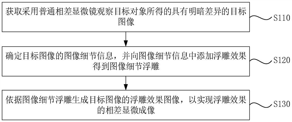
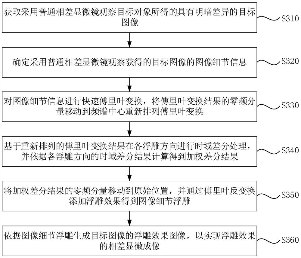
[0003] In related technologies, ordinary phase-contrast microscopes can only observe light and shade without layering or three-dimensionality, and cannot reflect structural changes inside cells. However, phase-contrast microscopes represented by differential interference contrast microscopy (DIC) and Hoffman modulation phase contrast microscopy are Oblique lighting and polarized light technology can be used to obtain a three-dimensional relief effect
However, the above-mentioned differential interference phase contrast microscope and Hoffman modulation phase contrast microscope have disadvantages such as relatively complex structure, large volume and high price, which lead to low practicability of relief imaging

Method used


Image

  • Phase difference microscopic imaging method and device, electronic equipment and storage medium
  • Phase difference microscopic imaging method and device, electronic equipment and storage medium
  • Phase difference microscopic imaging method and device, electronic equipment and storage medium

Examples


Embodiment Construction

[0029] The present invention will be further described in detail below in conjunction with the accompanying drawings and embodiments. It should be understood that the specific embodiments described here are only used to explain the present invention, but not to limit the present invention. In addition, it should be noted that, for the convenience of description, only some structures related to the present invention are shown in the drawings but not all structures.

[0030] Before discussing the exemplary embodiments in more detail, it should be mentioned that some exemplary embodiments are described as processes or methods depicted as flowcharts. Although the flowcharts describe various operations (or steps) as sequential processing, many of the operations (or steps) may be performed in parallel, concurrently, or simultaneously. In addition, the order of operations can be rearranged. The process may be terminated when its operations are complete, but may also have additional...


PUM


Abstract

The embodiment of the invention discloses a phase difference microscopic imaging method and device, electronic equipment and a storage medium. The method comprises the following steps: acquiring a target image with light and shade difference obtained by observing a target object by using a common phase contrast microscope; determining image detail information of the target image, and adding an embossment effect into the image detail information to obtain an image detail embossment; and generating an embossment effect image of the target image according to the image detail embossment so as to realize phase difference microscopic imaging of the embossment effect. By adopting the technical scheme provided by the invention, the layering embossment effect similar to a differential interference phase contrast microscope DIC or a Hoffman microscope is difficult to obtain by sample imaging of a common phase contrast microscope, and the light path design of the common phase contrast microscope does not need to be changed, Phase difference information in a target image which is shot by a common phase contrast microscope and comprises a target object is fully mined, and an embossment effect is added to image detail information, so that the target image has a stereoscopic embossment effect.

Description

technical field [0001] The embodiments of the present invention relate to the technical field of microscopic imaging, and in particular, to a phase contrast microscopic imaging method, device, electronic equipment, and storage medium. Background technique [0002] Phase-contrast microscopy can be used to observe unstained specimens. Due to the difference in the refractive index and thickness of the microstructure of each part of the cell, when the light wave passes through, the wavelength and amplitude do not change, only the phase changes. This phase difference cannot be observed by the human eye. . The phase contrast microscope changes the phase difference and uses light diffraction and interference phenomena to change the phase difference into an amplitude difference to observe living cells and unstained specimens. [0003] In related technologies, ordinary phase-contrast microscopes can only observe light and shade without layering or three-dimensionality, and cannot re...

Claims


Application Information

Patent Timeline
Patent Type & Authority Applications(China)
IPC IPC(8): G06T15/80G06T7/00G06T7/90
CPCG06T15/80G06T2207/10056G06T7/90G06T7/97
Inventor 张冀聪王海波
Owner HEFEI INNOVATION RES INST BEIHANG UNIV
Why Eureka
Try Eureka