Electrolytic chlorine production system suitable for high-hardness water quality
A high-hardness, water-quality technology, applied in the direction of water pollutants, natural water treatment, water/sewage treatment, etc., can solve problems such as scaling, achieve the effect of reducing the amount of scaling, simple operation, and easy shedding
- Summary
- Abstract
- Description
- Claims
- Application Information
AI Technical Summary
Problems solved by technology
Method used
Image
Examples
example 1
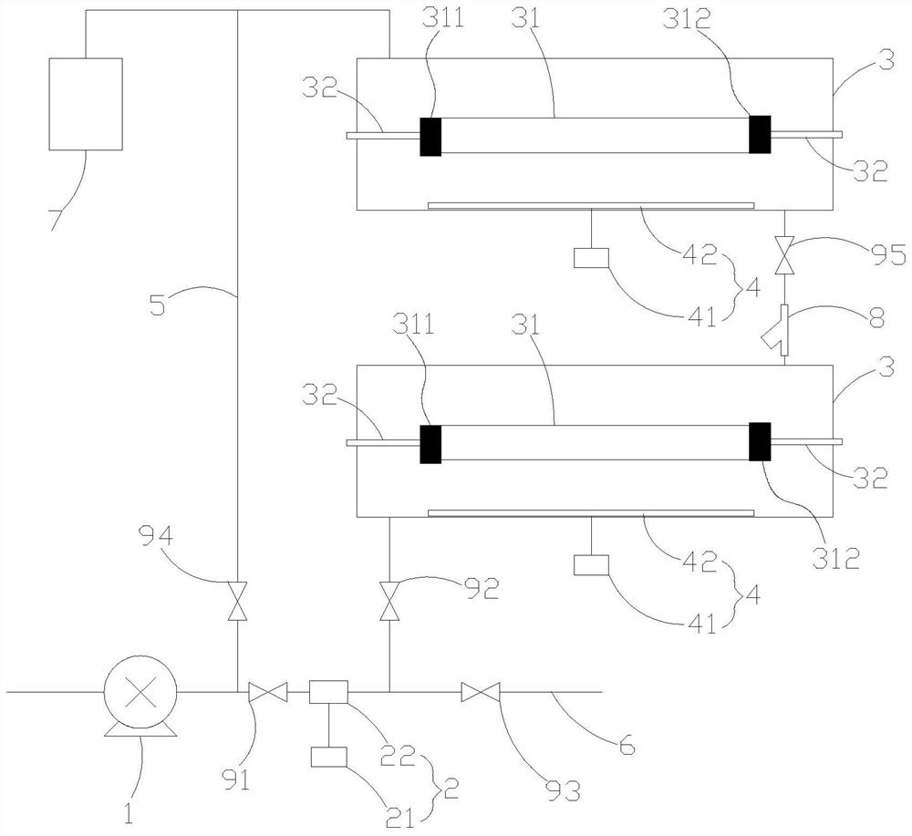
[0048] The electrolytic cell 3 adopts a horizontal tubular electrolytic cell, and the electrolytic cell 3 is made of plexiglass or glass fiber reinforced plastics. The pole core 31 composed of bipolar plates is installed at the axis of the electrolytic cell 3. The two ends of the pole core 31 are terminal anode 311 and terminal cathode respectively. 312 , the terminal anode 311 and the terminal cathode 312 are connected to the conductive rod 32 respectively. An ultrasonic vibrating plate 42 is installed below the pole core 31 , an electric pulse device 2 is installed on the pipeline before the entrance of the electrolytic tank 3 , and a filter device 8 is installed on the pipeline between two adjacent electrolytic tanks 3 .
[0049] Open the first valve 91, the second valve 92 and the fifth valve 95, close the third valve 93 and the fourth valve 94, start the water pump 1, turn on the electric pulse device 2, perform electric pulse treatment on the incoming water, and open the ...
example 2
[0052] The electrolytic cell 3 adopts a horizontal tubular electrolytic cell, and the electrolytic cell 3 is made of plexiglass or glass fiber reinforced plastics. The pole core 31 composed of bipolar plates is installed at the axis of the electrolytic cell 3. The two ends of the pole core 31 are terminal anode 311 and terminal cathode respectively. 312 , the terminal anode 311 and the terminal cathode 312 are connected to the conductive rod 32 respectively. An ultrasonic vibrating plate 42 is installed below the pole core 31 , an electric pulse device 2 is installed on the pipeline before the entrance of the electrolytic tank 3 , and a filter device 8 is installed on the pipeline between two adjacent electrolytic tanks 3 .
[0053] Open the first valve 91, the second valve 92 and the fifth valve 95, close the third valve 93 and the fourth valve 94, start the water pump 1, turn on the electric pulse device 2, perform electric pulse treatment on the incoming water, and open the ...
example 3
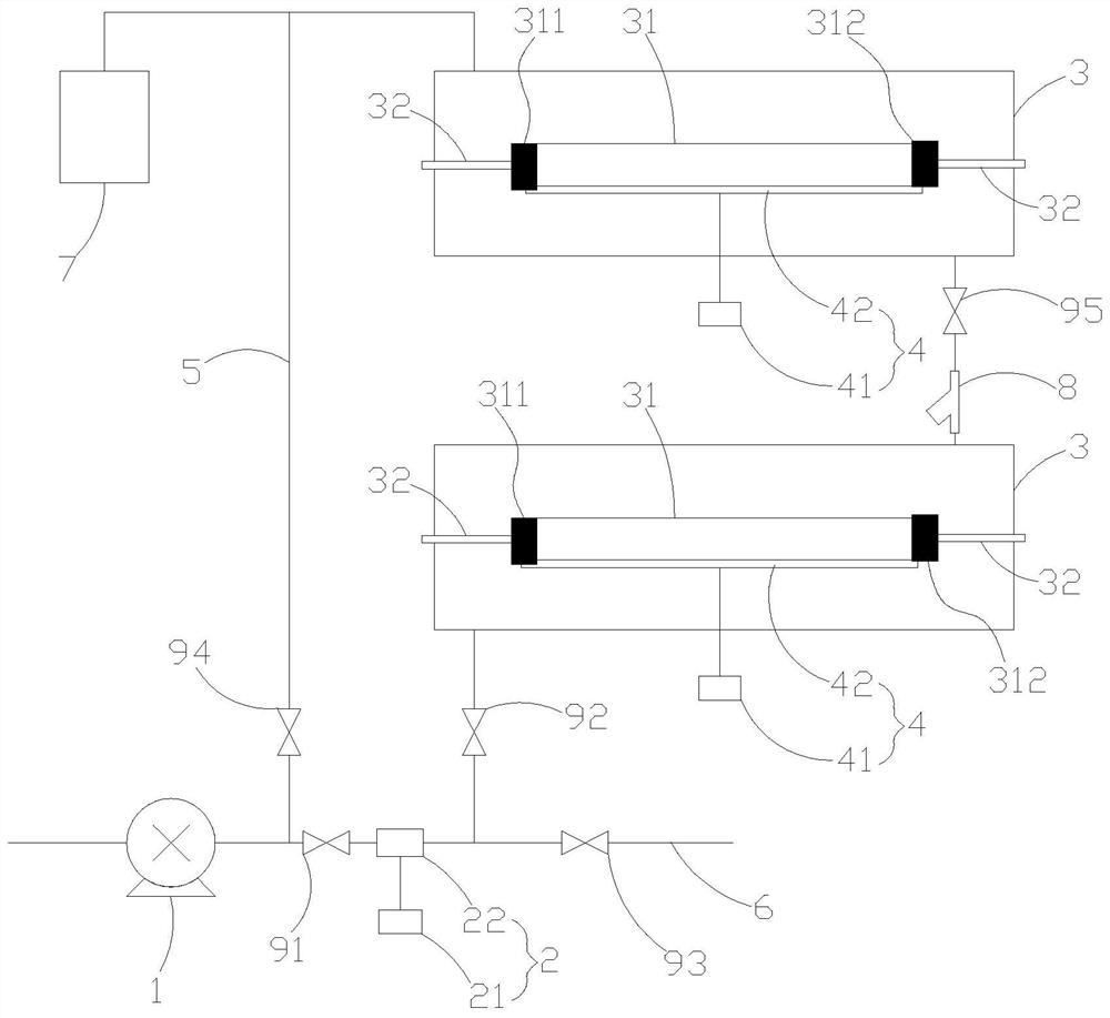
[0056] The electrolytic cell 3 adopts a horizontal tubular electrolytic cell, and the electrolytic cell 3 is made of plexiglass or glass fiber reinforced plastics. The pole core 31 composed of bipolar plates is installed at the axis of the electrolytic cell 3. The two ends of the pole core 31 are terminal anode 311 and terminal cathode respectively. 312 , the terminal anode 311 and the terminal cathode 312 are connected to the conductive rod 32 respectively. Ultrasonic vibration plate 42 is installed on one of the pole plates or a plurality of pole plates or all pole plates of pole core 31, and electric pulse device 2 is installed on the pipeline before the entrance of electrolytic tank 3, and two adjacent electrolytic tanks 3 Filter device 8 is installed on the pipeline between.
[0057] Open the first valve 91, the second valve 92 and the fifth valve 95, close the third valve 93 and the fourth valve 94, start the water pump 1, turn on the electric pulse device 2, perform ele...
PUM
 Abstract
Description
Claims
Application Information
 - R&D Engineer
- R&D Manager
- IP Professional
- Industry Leading Data Capabilities
- Powerful AI technology
- Patent DNA Extraction
Browse by: Latest US Patents, China's latest patents, Technical Efficacy Thesaurus, Application Domain, Technology Topic, Popular Technical Reports.
© 2024 PatSnap. All rights reserved.Legal|Privacy policy|Modern Slavery Act Transparency Statement|Sitemap|About US| Contact US: help@patsnap.com


