
High-voltage cable perforating equipment

A cable and high-voltage technology, applied in the field of high-voltage cable piercing equipment, can solve the problems of increased sliding resistance in the pipe, time-consuming and labor-intensive cable piercing, and affecting the piercing efficiency, so as to reduce improper operation, save manpower, and improve the piercing quality.

Inactive Publication Date: 2021-08-13
刘红国
View PDF0 Cites 3 Cited by
  • Summary
  • Abstract
  • Description
  • Claims
  • Application Information

AI Technical Summary

Problems solved by technology

[0005] Aiming at the deficiencies of the prior art, the present invention provides a high-voltage cable piercing device, which mainly solves the problem that the sliding resistance in the tube will increase, which makes the cable piercing time-consuming and laborious, and affects the piercing efficiency.

Method used


Image

  • High-voltage cable perforating equipment
  • High-voltage cable perforating equipment
  • High-voltage cable perforating equipment

Examples


Embodiment 1

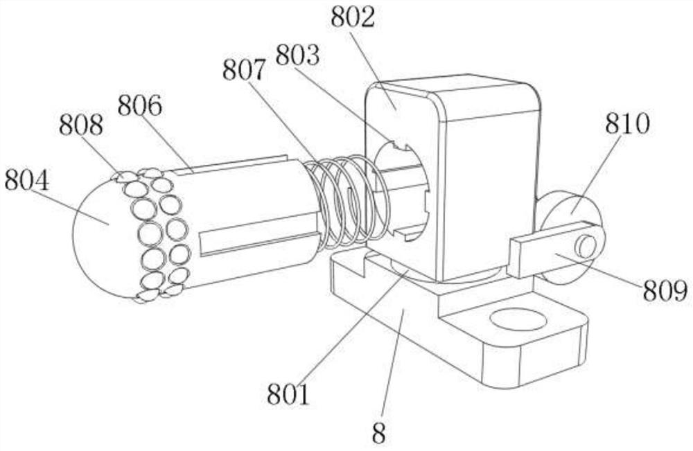
[0032] refer to Figure 1-Figure 5 , a high-voltage cable piercing equipment, including a bottom plate 1, a lifting mechanism fixed on one side of the bottom plate 1 by bolts, and a take-up reel 4 is inserted into the inside of the lifting mechanism, a pushing mechanism is arranged on one side of the bottom plate 1, and the top of the bottom plate 1 is fixed by bolts The base 8 is fixed, and the top of the base 8 is rotatably connected to a rotating shaft 801, and the top of the rotating shaft 801 is fixed with a block 802 by bolts, and one side of the block 802 is provided with a card hole, and the inner wall of the card hole is integrally formed with a protrusion 803 , the inner wall of the clamping hole is inserted with a perforated sleeve 804, and one side of the perforated sleeve 804 is provided with an insertion slot 806, and the insertion slot 806 is engaged with the protrusion 803, and one end of the perforated sleeve 804 is fixed with a first spring 807 by a bolt, The...

Embodiment 2

[0036] refer to Figure 6 , a high-voltage cable punching device, one end of the bottom plate 1 is fixed with two support frames 11 by bolts, and one side of the two support frames 11 is fixed with a fixed shaft 1101 by bolts, and the other end of the fixed shaft 1101 is plugged with the same A guide tube 1102, one end of the guide tube 1102 is fixed with a connecting snap ring 1103 by a bolt, and the other end of the connecting snap ring 1103 is fixed with a plug-in hose 1104 by a bolt, the inner wall of the plug-in hose 1104 is provided with a third spring 1105, and the guide tube 1102, the joint use of the connecting hose 1104 and the third spring 1105 can prevent the edge of the pipe from slipping on the surface of the cable when the hole is perforated, reducing the damage to the cable, and can also greatly reduce the impact on the cable caused by the edge of the pipe. The friction force improves the perforation efficiency.

[0037] The working principle of this embodimen...


PUM


Abstract

The invention relates to the technical field of electric power engineering tools, and discloses high-voltage cable perforating equipment which comprises a bottom plate. A lifting mechanism is fixedly connected to one side of the bottom plate, a winding disc is inserted into the inner side of the lifting mechanism, a pushing mechanism is arranged on one side of the bottom plate, and a base is fixedly connected to the top of the bottom plate. A rotating shaft is movably connected to the top of the base, a clamping block is fixedly connected to the top of the rotating shaft, a clamping hole is formed in one side of the clamping block in a clamped mode, a protruding block is integrally formed on the inner wall of the clamping hole, a perforating sleeve is movably connected to the inner wall of the clamping hole, an inserting groove is formed in one side of the perforating sleeve and connected with the protruding block in a clamped mode, and a first spring is fixedly connected to one end of the perforating sleeve. The equipment can prevent cable blockage from affecting perforation to a great extent, can improve the perforation efficiency so as to improve the cable laying quality, can also prevent rigid perforation of the cable and damage to the cable, can also perform perforation again, and improves the perforation quality.

Description

technical field [0001] The invention relates to the technical field of electrical engineering appliances, in particular to a high-voltage cable punching device. Background technique [0002] As we all know, in the construction of electric power engineering, it is often necessary to perforate the cable through the pipe. For the curved pipeline, in order to protect the cable and improve the efficiency of threading, the common method is to wrap the top of the cable, and then carry out piercing or perforation. Or drag the cable out of the pipe with an iron wire at one end, which is often time-consuming and laborious, and it is easy to cause damage to the cable and affect the efficiency of cable laying. Therefore, a high-efficiency high-voltage cable punching device is needed. [0003] At present, most of the existing high-voltage cable piercing equipment has the following disadvantages: the sliding resistance in the tube will increase, making cable piercing time-consuming and la...

Claims


Application Information

Patent Timeline
Patent Type & Authority Applications(China)
IPC IPC(8): H02G1/06H02G1/08B65H54/44B65H54/553B65H49/38B65H57/14
CPCB65H49/38B65H54/44B65H54/553B65H57/14H02G1/06H02G1/08
Inventor 刘红国
Owner 刘红国
Learn More