Construction method for dismantling large-span pre-stressed cast-in-place box girder

A construction method and prestressing technology, which is applied in bridges, bridge materials, bridge maintenance, etc., can solve problems such as high risk, complex stress in the secondary system of the structure, and heavy weight of cutting blocks, so as to reduce potential safety hazards and ensure safety. Quick demolition, convenient and quick construction

Inactive Publication Date: 2021-08-10
BEIJING MUNICIPAL CONSTR +1
View PDF0 Cites 9 Cited by
  • Summary
  • Abstract
  • Description
  • Claims
  • Application Information

AI Technical Summary

Problems solved by technology

[0004] This method of bridge demolition is only suitable for the demolition of bridges with smaller beams and better integrity of box girders, while the demolition of long-span prestressed cast-in-place box girders is often more complicated, limited by the operating conditions of large-scale equipment, and the traffic conditions Restrictions, high difficulty in structural bearing capacity assessment, restrictions on demolition equipment and operating environment restrictions, etc., the overall characteristics of bridge demolition are high risk, and the secondary system of the structure is complex in terms of stress. For example, the girder bridge adopts prestressed steel after non-destructive cutting If the bridge beam fails completely, it is necessary to conduct a secondary evaluation of the structural bearing capacity and set up a reasonable temporary support system. When the size of the bridge box girder is large, most people will choose to put all the pieces in one size fits all, starting from the broken end or the middle of the box girder. , the weight of the cutting block after cutting the whole box girder is large, and the impact load on the temporary support of the lower part is relatively large.

Method used


Image

  • Construction method for dismantling large-span pre-stressed cast-in-place box girder
  • Construction method for dismantling large-span pre-stressed cast-in-place box girder
  • Construction method for dismantling large-span pre-stressed cast-in-place box girder

Examples


Embodiment Construction

[0043] The following is attached Figure 1-9 The application is described in further detail.

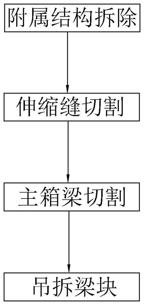
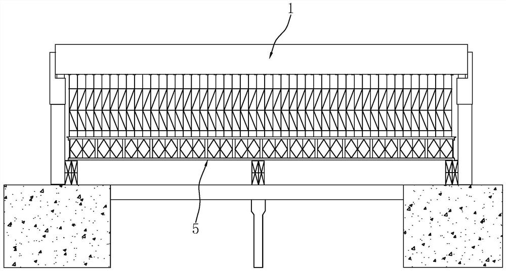
[0044] refer to figure 1 and figure 2 , for the embodiment of the present application discloses a construction method for demolition of long-span prestressed cast-in-place box girders, comprising the following steps:

[0045] S1. Construction preparation:

[0046] 1. Plan the site, designate the crushing area, and set up safe passages;

[0047] 2. For safe construction, do a good job of safety warnings, instructions and signs according to the requirements of double standards;

[0048] 3. River water is used for construction water;

[0049] 4. According to the power consumption of mechanical equipment, make preparations for power-on;

[0050] 5. Plan, prepare and try out construction machinery, construction materials and construction tools in advance;

[0051] 6. Conduct construction safety education for staff and provide detailed technical disclosure;

[0052] 7. Stack truc...


PUM


Abstract

The invention relates to a construction method for dismantling a large-span pre-stressed cast-in-place box girder, which comprises the following steps: S1, dismantling an accessory structure, and dismantling bridge deck pavement and traffic facilities on a box girder; S2, cutting an expansion joint, breaking concrete at the expansion joint of the box girder, and cutting off connecting steel bars, angle steel and bolts at the expansion joint; S3, cutting the box girder, firstly, adopting a disk lock scaffold for building a dismantling scaffold which tightly abuts against the bottom plate of the concrete box girder and the wing plates on both sides, and cutting the box girder by adopting a diamond wire saw, wherein the dismantling sequence of the box girder is as follows: symmetrically cutting wing plates on two sides, releasing web steel strands, cutting a left web, cutting a box type top plate, cutting a right web and cutting a box chamber bottom plate; and S4, hoisting and dismantling the beam blocks, and specifically, transferring and abandoning the cut beam blocks to a designated place through hoisting equipment. The construction method has the effect of safely and rapidly dismantling the large-span pre-stressed cast-in-place box girder.

Description

technical field [0001] The present application relates to the technical field of building construction, in particular to a construction method for demolishing large-span prestressed cast-in-place box girders. Background technique [0002] A kind of beam in box girder bridge engineering, refer to Figure 4 , including a top plate 11, a bottom plate 12 and two webs 13, the inside is hollow, and there are wing plates 14 on both sides of the top plate, similar to a box, hence the name. According to the production method, box girders are mainly divided into two types, one is prestressed reinforced concrete box girder, and the other is steel box girder. Among them, the prestressed reinforced concrete box girder is constructed on site. In addition to the longitudinal prestress, some also have transverse prestress; the steel box girder is generally processed in the factory and then transported to the site for installation. There are all steel structures, and some Add reinforced con...

Claims


Application Information

Patent Timeline
Patent Type & Authority Applications(China)
IPC IPC(8): E01D24/00E01D2/04E01D101/28
CPCE01D2/04E01D22/00E01D2101/28
Inventor 张鹏周阳孙强马少军靳利军高明生吴进科王鹏张伟汤明王宁赵建康张红梅曹凯汪艳明王佳特王燕
Owner BEIJING MUNICIPAL CONSTR
Why Eureka
Try Eureka