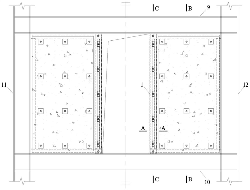
Holed buckling-restrained shear wall with buckling-restrained fishplates and construction method
A buckling restraint, fishplate technology, applied in the direction of walls, earthquake-proof, building components, etc., can solve the problems of reduced bearing capacity, easy protruding of the wall at the edge of the hole, weakened seismic performance of the structure, etc., to achieve the effect of ensuring stability
- Summary
- Abstract
- Description
- Claims
- Application Information
AI Technical Summary
Problems solved by technology
Method used
Image
Examples
specific Embodiment approach 1
[0026] Specific implementation mode one: combine Figure 1-Figure 11 To illustrate this embodiment, the open buckling-resistant shear wall with buckling-constrained fishplates includes an upper frame beam 9, a lower frame beam 10, a left frame column 11, a right frame column 12, and a plurality of plates 15 , it also includes two buckling-constrained fishplates 1 and two perforated steel plates 8; the upper frame beam 9, the lower frame beam 10, the left frame column 11 and the right frame column 12 form a rectangular frame, and the two buckling-constrained fishplates The plate 1 is vertically installed in the rectangular frame, and two perforated steel plates 8 are symmetrically arranged in the rectangular frame, and each perforated steel plate 8 is fixedly connected with a buckling-constrained fishplate 1, and each perforated steel plate 8 passes through multiple Each plate body 15 is fixedly connected with the inner side wall of the rectangular frame. In this embodiment, t...
specific Embodiment approach 2
[0027] Specific implementation mode two: combination figure 1 and Figure 11 Describe this embodiment, the open buckling-resistant shear wall with buckling-restrained fishplates described in this embodiment, the buckling-restrained fishplate 1 includes the core steel plate 2, the upper connection support 4, the lower connection support 5 and two Two limb-constrained steel pipes 3; the inner core steel plate 2 is welded and installed on a holed steel plate 8, two double-legged steel pipes 3 are symmetrically installed on the outside of the inner core steel plate 2 and the holed steel plate 8, and the upper connecting support 4 is welded and installed on the upper frame On the bottom of the beam 9, the lower connecting support 5 is welded on the top of the lower frame beam 10. The core steel plate 2 is flush with the edge of the hole and placed in the hole steel plate 8, and the edge of the hole steel plate 8 protrudes a length of the thickness of the hole steel plate 8 compare...
specific Embodiment approach 3
[0028] Specific implementation mode three: combination figure 1 , Figure 5 , Figure 6 and Figure 11 Describe the present embodiment, the opening anti-buckling shear wall with buckling restraint fishplate described in this embodiment, the upper connecting support 4 includes a first upper connecting plate 4-1 and a second upper connecting plate 4-2; Both the first upper connecting plate 4-1 and the second upper connecting plate 4-2 are processed with oval pin holes, and the first upper connecting plate 4-1 and the second upper connecting plate 4-2 are welded and installed on the upper frame beam 9 On the bottom end, the core steel plate 2 and the holed steel plate 8 are installed between the first upper connecting plate 4-1 and the second upper connecting plate 4-2. There is a gap between the top of the double limb restraining steel pipe 3 and the upper connection support 4, and the width of the gap is greater than 1 / 20 of the width of the inner core steel plate 2. Other ...
PUM
 Abstract
Description
Claims
Application Information
 - R&D
- Intellectual Property
- Life Sciences
- Materials
- Tech Scout
- Unparalleled Data Quality
- Higher Quality Content
- 60% Fewer Hallucinations
Browse by: Latest US Patents, China's latest patents, Technical Efficacy Thesaurus, Application Domain, Technology Topic, Popular Technical Reports.
© 2025 PatSnap. All rights reserved.Legal|Privacy policy|Modern Slavery Act Transparency Statement|Sitemap|About US| Contact US: help@patsnap.com


