


Quick Research
Generate reliable direction feasibility study reports for your R&D in just a few steps.

Technical Q&A
Discover and master advanced knowledge NOW. Basics, ideas, possibilities, all at once.

Find Solutions
As an expert in R&D theories, this can generate solutions to your technical problems instantly.

Evaluate Feasibility
Analyze your overall solution with one click, know your potential R&D risks in advance.

Monitor Landscape
Get weekly tech updates, stay abreast of the latest tech innovations and key insights.
Fine grinding device for food machining
A fine grinding and food processing technology, which is applied in tea processing and grain processing before extraction, can solve the problems of uneven grinding of matcha powder, high labor intensity of workers, and unhygienic matcha powder, so as to solve the problem of uneven grinding and reduce work Volume, improve the effect of fineness
- Summary
- Abstract
- Description
- Claims
- Application Information
AI Technical Summary
Problems solved by technology
Method used
Image

Examples
Embodiment 1
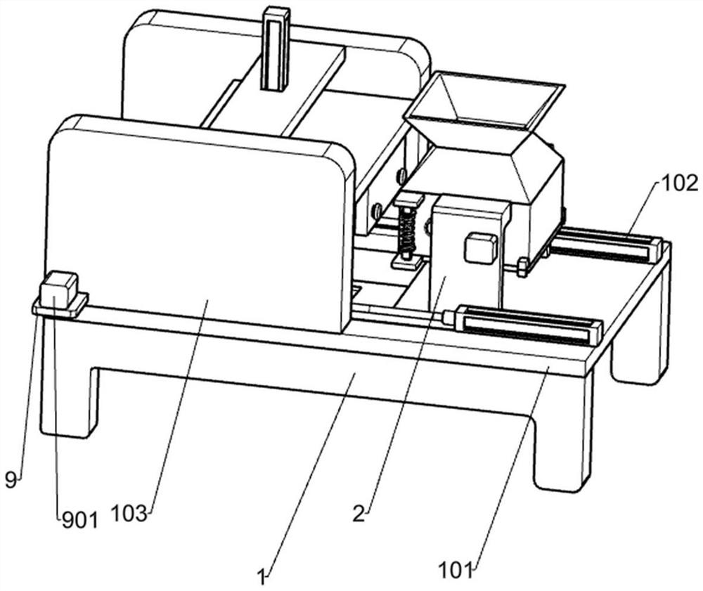
[0099] A fine grinding device for food processing, such as Figure 1-10 As shown, it includes a frame 1, a U-shaped plate 101, an electric push rod 102, a support plate 103, a guide rail 104, a guide block 105, a top plate 209, a crushing mechanism and a grinding mechanism, and there are two frame 1s. The U-shaped plate 101 is fixed on the top of the two racks 1, and the right end of the U-shaped plate 101 has a square hole. There are two electric push rods 102. One 103 is two, support plate one 103 is symmetrically fixed on the top of U-shaped plate 101, support plate one 103 is located on the left side of electric push rod one 102, guide rail one 104 is two, guide rail one 104 is symmetrically arranged on U-shaped plate 101 , the guide block 105 is two, the guide block 105 is slidably connected to the guide rail 104, the lower end of the top plate 209 is set in the square hole of the U-shaped plate 101, the top plate 209 has a through hole, and the lower end of the through h...
Embodiment 2
[0102] further, such as Figure 4-6 As shown, the grinding mechanism includes connecting plate 1 4, guide rail 2 402, guide block 2 401, connecting plate 2 403, electric push rod 2 404, supporting plate 2 405, connecting plate 3 406, guide block 3 407, and guide post 1 408, grinding plate 1 409, guide rail 3 4091, spring 1 4010, slideway 1 4011, orifice plate 5, L-shaped inclined block 501, guide post 2 502, bottom plate 1 503, support column 1 504, connecting rod 505, support column 2 506, support column 3 507 and grinding plate 2 5071, both ends of connecting plate 1 4 are horizontally fixed to support plate 1 103, two guide rails 2 402 are symmetrically installed on the inside of support plate 1 103, and there are two guide blocks 2 401, Guide block 2 401 is slidingly connected to guide rail 2 402, guide block 2 401 is installed on both sides of connecting plate 2 403, electric push rod 2 404 is installed in the middle of connecting plate 1 4, and the top of electric push r...
Embodiment 3
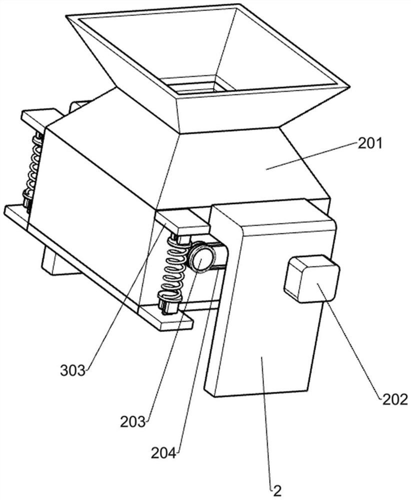
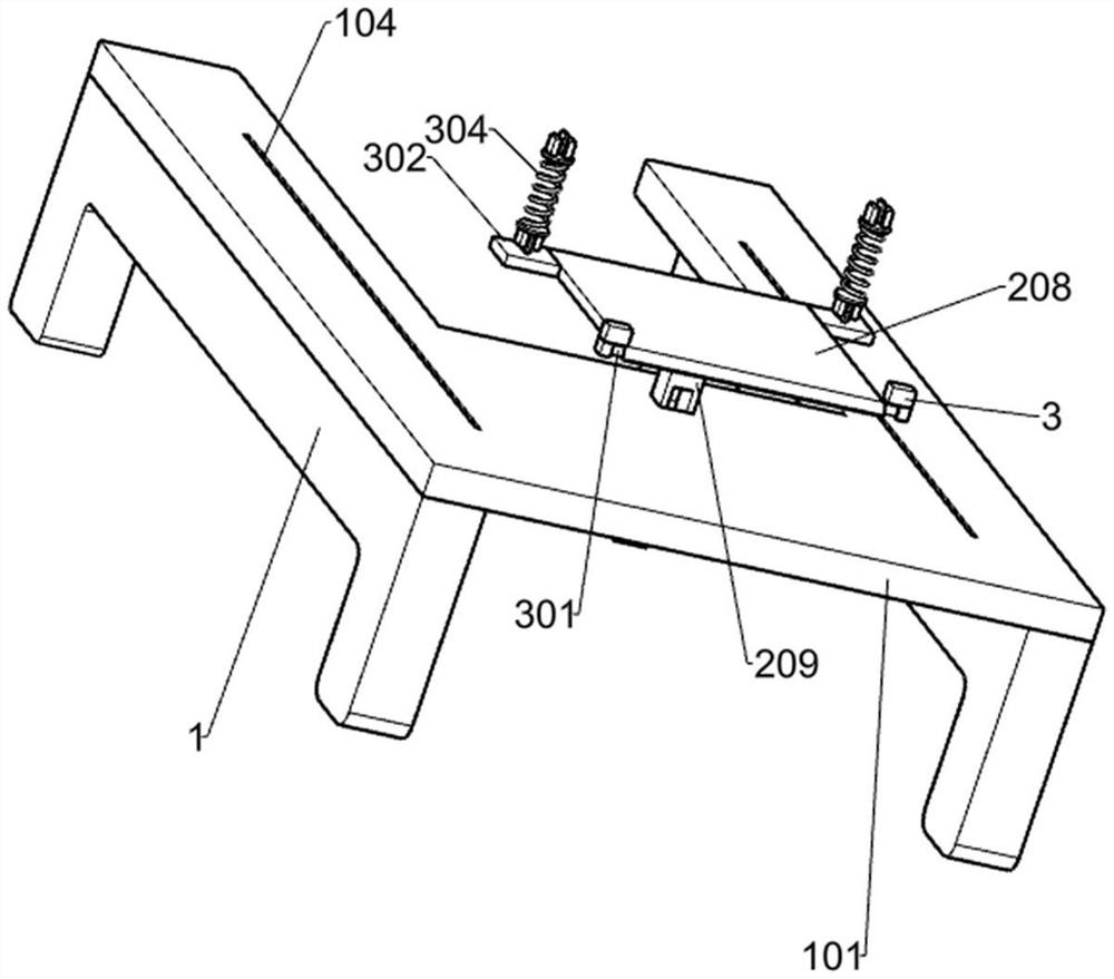
[0105] further, such as Figure 3-10As shown, it also includes a blanking mechanism. The blanking mechanism includes a mounting plate 2010, an elastic member 2011, a supporting plate 2 3, a rotating shaft 2 301, a mounting plate 2 302, a mounting plate 3 303 and an elastic member 2 304. There are two plates 1 2010, the mounting plate 1 2010 is symmetrically fixed on both sides of the top plate 209, the elastic member 1 2011 is two, one end of the elastic member 1 2011 is fixed to the mounting plate 2010, and the other end is fixed to the U-shaped plate 101, the support plate 2 3 is L-shaped, the two support plates 3 are respectively fixed on the outside of the hopper 201, the rotating shaft 2 301 is installed on the side of the baffle plate 1 208, and the two ends of the rotating shaft 301 are rotatably connected to the support plate 2 3, There are two mounting plates 302, the mounting plate 2 302 is symmetrically fixed on both sides of the baffle plate 1 208, the two mounting...
PUM
 Abstract
Description
Claims
Application Information
 - R&D Engineer
- R&D Manager
- IP Professional
- Industry Leading Data Capabilities
- Powerful AI technology
- Patent DNA Extraction
Browse by: Latest US Patents, China's latest patents, Technical Efficacy Thesaurus, Application Domain, Technology Topic, Popular Technical Reports.
© 2024 PatSnap. All rights reserved.Legal|Privacy policy|Modern Slavery Act Transparency Statement|Sitemap|About US| Contact US: help@patsnap.com