
Polishing slurry composition for sti process

A technology of composition and slurry, which is applied in the direction of polishing composition containing abrasives, other chemical processes, water-based dispersants, etc., can solve problems such as scratches and large depression of insulating film, so as to prevent over-polishing and excellent flatness The effect of high degree and high removal speed

Inactive Publication Date: 2021-07-30
K C TECH
View PDF2 Cites 0 Cited by
  • Summary
  • Abstract
  • Description
  • Claims
  • Application Information

AI Technical Summary

Problems solved by technology

However, when a cell type pattern is polished using a slurry additive liquid composition having a negative zeta potential, defects, scratches, etc. often occur, and there is also a problem that the degree of sinking of the insulating film is large during excessive polishing.

Method used


Image

  • Polishing slurry composition for sti process
  • Polishing slurry composition for sti process
  • Polishing slurry composition for sti process

Examples


Embodiment 1 to 7

[0082] As shown in Table 1, an additive liquid was prepared, and a polishing liquid including ceria polishing particles having a particle size of 150 nm was prepared. That is, the slurry composition for the STI polishing process was prepared at a ratio of polishing liquid: water: additive liquid of 1:6:3.

[0083] [Polishing condition]

[0084] 1. Polishing device: AP-300 (300mm, KCTECH company)

[0085] 2. Pad: IC 1000 (DOW company)

[0086] 3. Polishing time: 60 seconds

[0087] 4. Platen RPM (Platen RPM): 93rpm

[0088] 5. Spindle RPM (Spindle RPM): 87rpm

[0089] 6. Pressure: 3psi

[0090] 7. Flow rate: 250ml / min

[0091] 8. Chips used:

[0092] Wafer: PE-TEOS P-Poly

[0093] Pattern wafer: STI polysilicon pattern wafer groove depth

[0094] The polishing slurry compositions that are used for the STI process of embodiment and comparative example are shown in table 1, and the removal rate (RemovalRate : RR).

[0095] 【Table 1】

[0096]

[0097]

[...


PUM


Abstract

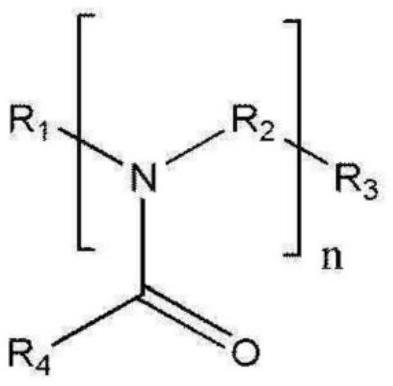
The present invention relates to a polishing slurry composition for an STI process and, more specifically, to a polishing slurry composition for an STI process, the polishing slurry composition comprising: a polishing solution including polishing particles; and an additive solution containing a polymer having an amide bond, and a polysilicon film polishing barrier inclusive of a monomer having three or more chains linked to one or more atoms.

Description

technical field [0001] The present invention relates to a polishing slurry composition for an STI process capable of reducing dishing while having a high polishing rate. Background technique [0002] As semiconductor elements become more diverse and highly integrated, a technology capable of forming fine patterns is used, which makes the surface structure of semiconductor elements more and more complicated, and the step difference of the surface film becomes larger and larger. In the process of manufacturing semiconductor elements, chemical mechanical polishing (CMP, chemical mechanical polishing) planarization technology is used to remove the step difference formed on a specific film of a substrate. Insulation for shallow trench isolation (STI) that is used as a process for removing excessively formed insulating films for interlayer insulation and insulation between interlayer insulating films (interlayer dielectric, ILD) and chips (chips). It is used in the planarization ...

Claims


Application Information

Patent Timeline
Patent Type & Authority Applications(China)
IPC IPC(8): C09G1/02C09K3/14C09G1/04
CPCC09K3/14C09G1/02C09K3/1409C09G1/04C09K3/1463
Inventor 金廷润黄晙夏朴光洙梁海元
Owner K C TECH
Learn More