
Method for suppressing neutral-point potential balance and common-mode voltage of three-phase three-level inverter

A three-level inverter and common-mode voltage technology, which is applied in the direction of electrical components, output power conversion devices, and conversion of AC power input to DC power output, can solve the problem of high switching loss, reduce switching loss, reduce The effect of harmonics

Active Publication Date: 2021-07-27
ANHUI UNIVERSITY OF ARCHITECTURE
View PDF5 Cites 9 Cited by
  • Summary
  • Abstract
  • Description
  • Claims
  • Application Information

AI Technical Summary

Problems solved by technology

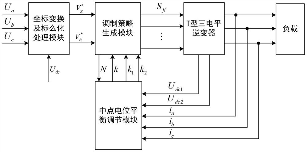
[0011] The present invention aims at the problem of high switching loss in the common-mode voltage suppression method of the current three-phase three-level inverter, and proposes a method for neutral-point potential balance and common-mode voltage suppression of the three-phase three-level inverter. It is to select a variety of virtual vectors to make the pulse sequence switch smoothly, so as to effectively reduce the switching times of the switching tube of the three-level inverter and reduce the switching loss while having the midpoint potential balance capability

Method used


Image

  • Method for suppressing neutral-point potential balance and common-mode voltage of three-phase three-level inverter
  • Method for suppressing neutral-point potential balance and common-mode voltage of three-phase three-level inverter
  • Method for suppressing neutral-point potential balance and common-mode voltage of three-phase three-level inverter

Examples


Embodiment Construction

[0177] The method of the present invention will be clearly and completely described below in conjunction with the accompanying drawings.

[0178] Figure 5 It is a hardware schematic diagram of an embodiment of a T-type three-level inverter midpoint potential balance and common-mode voltage suppression method. The embodiment selects DSP+FPGA platform to realize. Among them, the DSP model is TMS320F28335, and the FPGA model is EP2C20F48418N. The reference voltage vector V is generated by DSP ref The g-axis component of h axis component Pass the g-axis component with address XA=0 Pass the h-axis component with address XA=1 Send to FPGA through 16-bit data bus XD[15:0], and write signal by external interface or external interface area strobe signal Trigger the FPGA to acquire data. Then, the acquisition of the sector number N, the small area number n, and the number r of the sector basic voltage vector in the sequence G is completed in the FPGA, and the sampling ci...


PUM


Abstract

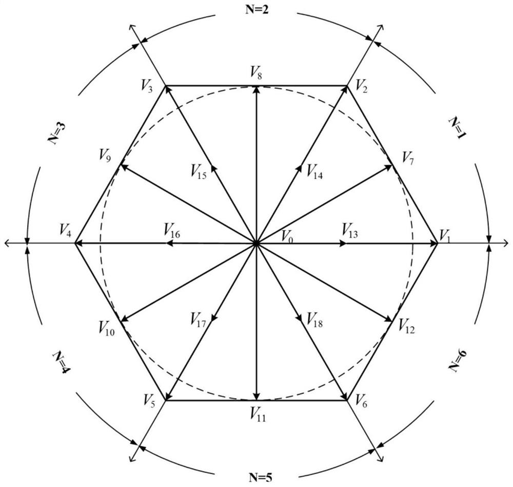
The invention provides a method for suppressing the neutral-point potential balance and common-mode voltage of a three-phase three-level inverter, and relates to the technical field of power electronics. The method comprises the following steps of selecting a sector basic voltage vector with small common-mode voltage to participate in the synthesis of a virtual vector, and suppressing the common-mode voltage; adopting a plurality of virtual small vectors to smoothly switch the pulse sequences of a same area, the adjacent small areas and the adjacent large areas. On the basis, the amplitude of the virtual vector is changed by detecting the voltage value of the voltage dividing capacitor end at the direct current side and the three-phase current value at the load side in real time, then the action time of the virtual vector in a carrier period is changed, and finally the neutral-point potential balance and common-mode voltage suppression are achieved. Due to the fact that multiple virtual vectors are selected, the neutral-point potential balance and common-mode voltage suppression are achieved, and meanwhile the switching loss is low.

Description

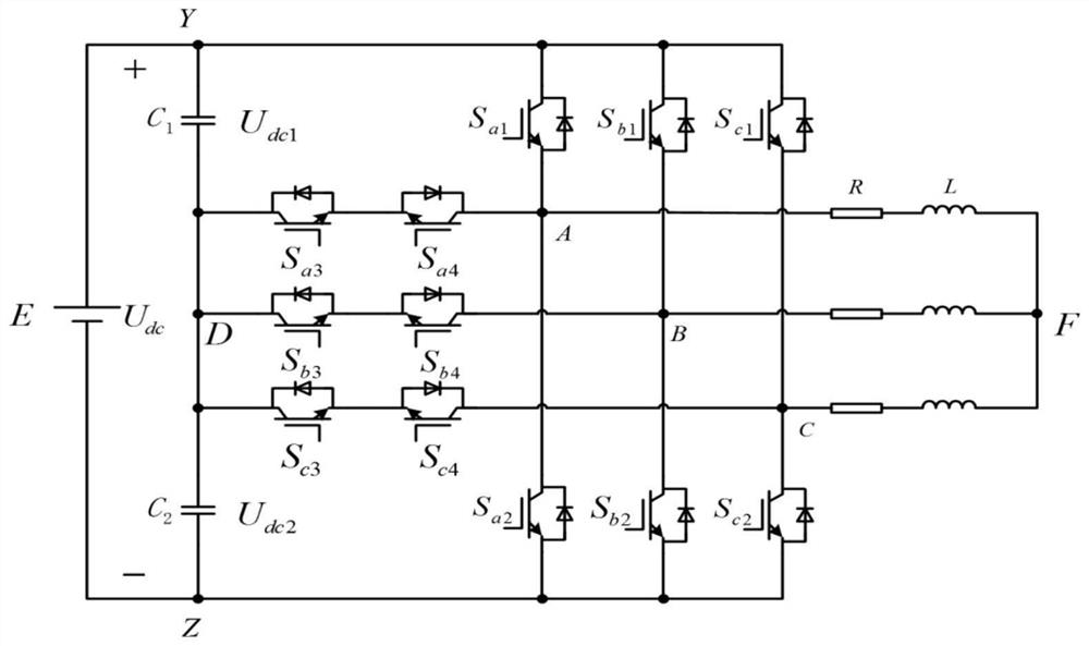
technical field [0001] The invention relates to the technical field of power electronics, in particular to a method for neutral-point potential balance and common-mode voltage suppression of a three-phase three-level inverter. Background technique [0002] Limited by the current voltage level of switching devices, traditional two-level converters cannot meet the needs of medium and high voltage level power conversion. The three-level inverter uses low-voltage devices to achieve high-voltage output, avoiding direct series connection of devices, low harmonics, and small electromagnetic interference. Widely used in high-voltage frequency conversion speed regulation, new energy power generation, power system, electrified transportation and other fields. [0003] Current mainstream three-level inverter topologies include diode-clamped three-level inverters and T-type three-level inverters. Both topologies are similar in principle and work with exactly the same modulation strate...

Claims


Application Information

Patent Timeline
Patent Type & Authority Applications(China)
IPC IPC(8): H02M7/5387H02M1/12
CPCH02M7/53875H02M1/12
Inventor 李善寿陶勇王浩马枭杰
Owner ANHUI UNIVERSITY OF ARCHITECTURE
Learn More