


Quick Research
Generate reliable direction feasibility study reports for your R&D in just a few steps.

Technical Q&A
Discover and master advanced knowledge NOW. Basics, ideas, possibilities, all at once.

Find Solutions
As an expert in R&D theories, this can generate solutions to your technical problems instantly.

Evaluate Feasibility
Analyze your overall solution with one click, know your potential R&D risks in advance.

Monitor Landscape
Get weekly tech updates, stay abreast of the latest tech innovations and key insights.
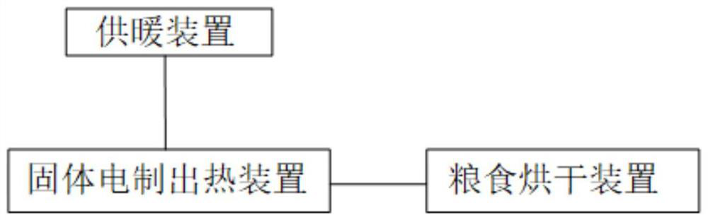
Electric heating and heat storage grain drying and clean heating combined system based on waste heat recovery
A waste heat recovery and grain drying technology, applied in hot water central heating systems, heating systems, grain drying, etc., can solve problems such as low drying efficiency, air pollution, and single use of solid electric heat storage devices
- Summary
- Abstract
- Description
- Claims
- Application Information
AI Technical Summary
Problems solved by technology
Method used
Image

Examples
Embodiment 1
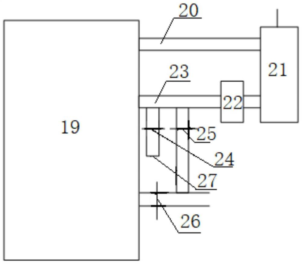
[0057] In the non-heating season, this system is only used for grain drying, and there is only a difference in heat source from the traditional grain drying system. The solid heat accumulator furnace 19 utilizes the low-valley electricity at night to heat, and outputs hot air to the outside when the grain is dried, and opens the third baffle plate 26 and the first baffle plate 24 .
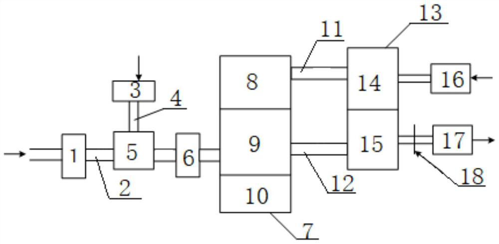
[0058] During the drying operation, the high-temperature hot air is sent into the drying air duct 2 through the first induced draft fan 1. The present invention adopts a Y-shaped staggered air duct mode, such as Figure 5 As shown, the air volume is controlled by adjusting the first regulating valve 38 and the second regulating valve 40, enters the temperature regulating device 5, and controls the temperature in different ranges according to the needs of different drying operations, and uses the second induced draft fan 6 to pass through Drying air duct 2 sends hot blast into the grain drying towe...
Embodiment 2
[0061] In the heating season, this system is not only used for grain drying, but also used for heating in winter. The solid heat accumulator furnace 19 is heated by electricity in the low valley at night. Since the heating is 24h full-time heating, when grain drying is required, the hot air is output to the outside, the third baffle 26 is closed, the second baffle 25 is opened, and the second baffle 25 is opened. A baffle plate 24 sends the heated part of the hot air into the grain drying system.
[0062] During the drying operation, the high-temperature hot air is sent into the drying air duct 2 through the first induced draft fan 1. The present invention adopts a Y-shaped staggered air duct mode, such as Figure 5 As shown, the air volume is controlled by adjusting the first regulating valve 38 and the second regulating valve 40, enters the temperature regulating device 5, and controls the temperature in different ranges according to the needs of different drying operations,...
PUM
 Abstract
Description
Claims
Application Information
 - R&D Engineer
- R&D Manager
- IP Professional
- Industry Leading Data Capabilities
- Powerful AI technology
- Patent DNA Extraction
Browse by: Latest US Patents, China's latest patents, Technical Efficacy Thesaurus, Application Domain, Technology Topic, Popular Technical Reports.
© 2024 PatSnap. All rights reserved.Legal|Privacy policy|Modern Slavery Act Transparency Statement|Sitemap|About US| Contact US: help@patsnap.com