


Quick Research
Generate reliable direction feasibility study reports for your R&D in just a few steps.

Technical Q&A
Discover and master advanced knowledge NOW. Basics, ideas, possibilities, all at once.

Find Solutions
As an expert in R&D theories, this can generate solutions to your technical problems instantly.

Evaluate Feasibility
Analyze your overall solution with one click, know your potential R&D risks in advance.

Monitor Landscape
Get weekly tech updates, stay abreast of the latest tech innovations and key insights.
Continuous reactor suitable for high-viscosity and high-solid-content reactant system and application
A high solid content, reactor technology, applied in chemical instruments and methods, chemical/physical processes, etc., can solve problems such as inability to apply multi-stage loop reactors, easy short-circuiting of materials and solid particles, affecting the environment and worker safety, etc. To achieve the effect of increasing the interphase contact area and transfer coefficient, improving the reaction conversion rate and reaction rate, and being easy to scale up in industry
- Summary
- Abstract
- Description
- Claims
- Application Information
AI Technical Summary
Problems solved by technology
Method used
Image


Examples
Embodiment 1
[0043] Example 1 is the application of a continuous primary reactor with high viscosity and high solid content reaction system in the synthesis of 2-amino-8-naphthol-6-sulfonic acid.
[0044] Such as figure 1 , image 3 with Figure 4 Shown:
[0045] The reactor includes a shell 1, a shrinking diversion cone 2, an inner sleeve 3, a divergent diversion cone 4, a structured packing 5, a gas distributor 6, and a hydrocyclone 7; the internal parts of the reactor are from bottom to top: Gas distributor 6, shrinking diversion cone 2, inner sleeve 3 and structured packing 5, divergent diversion cone 4, hydrocyclone 6; the reactor is provided with gas inlet 8, upper feed inlet 11, upper outlet A feed port 12, a lower feed port 11, a lower discharge port 12 and a gas discharge port 13. The lower diversion cone of the inner sleeve 3 is a shrinking diversion cone 2, the inside of the inner sleeve 3 is an ascending area, and the outside of the inner sleeve 3 is a descending area; the ...
Embodiment 2
[0049] Example 2 is the application of a continuous secondary reactor with high viscosity and high solid content reaction system in the synthesis of methyl isocyanate.
[0050] Such as figure 2 , image 3 with Figure 4 Shown:
[0051] The reactor includes a shell 1, a shrinking diversion cone 2, an inner sleeve 3, a divergent diversion cone 4, a structured packing 5, a gas distributor 6, and a hydrocyclone 7; the internal parts of the reactor are from bottom to top: Gas distributor 6, shrinking diversion cone 2, inner sleeve 3 and structured packing 5, divergent diversion cone 4, hydrocyclone 6; the reactor is provided with gas inlet 8, upper feed inlet 11, upper outlet A feed port 12, a lower feed port 11, a lower discharge port 12 and a gas discharge port 13. The lower guide cone of the two inner sleeves 3 is a contraction guide cone 2, the inside of the inner sleeve 3 is an ascending area, and the outside of the inner sleeve 3 is a descending area. The lower guide co...
Embodiment 3
[0056] Example 3 is the application of a continuous three-stage three-column reactor with high viscosity and high solid content reactant system in the synthesis of 2,4-dichlorophenoxyacetic acid from sodium 2,4-dichlorophenate and sodium chloroacetate.
[0057] Such as Image 6 Shown:
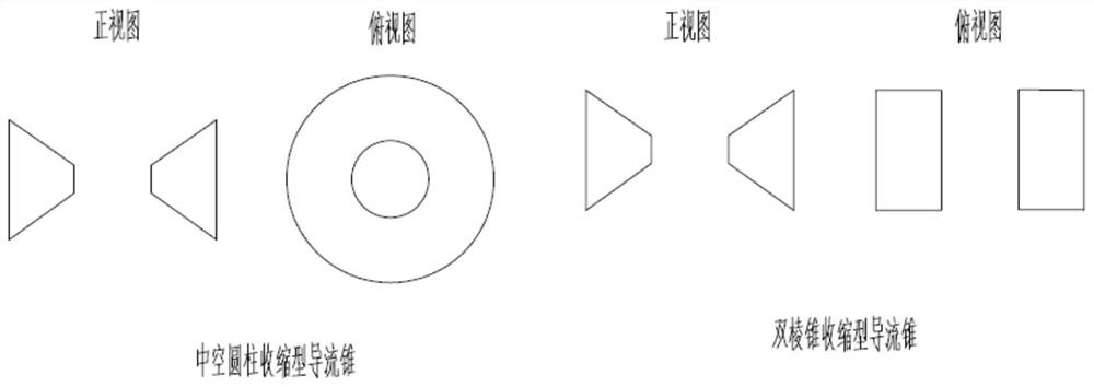
[0058] M-level N-column reactor M≤50, N≤50, the cross-sectional area between the inner sleeves 3 in the horizontal direction is equal to the cross-sectional area of the inner sleeves 3 . The shell 1 of the M-level N-column reactor is rectangular or circular, and the rectangular shell is preferred when the operating pressure is normal pressure, and the circular shell is preferred when the operating pressure is negative pressure or positive pressure; the inner sleeve 3 is a truss , the diversion cones are all divergent diversion cones 4, the diversion cones in contact with the housing are prism divergent diversion cones 4, and the diversion cones that are not in contact with the housing are bi...
PUM
 Abstract
Description
Claims
Application Information
 - R&D Engineer
- R&D Manager
- IP Professional
- Industry Leading Data Capabilities
- Powerful AI technology
- Patent DNA Extraction
Browse by: Latest US Patents, China's latest patents, Technical Efficacy Thesaurus, Application Domain, Technology Topic, Popular Technical Reports.
© 2024 PatSnap. All rights reserved.Legal|Privacy policy|Modern Slavery Act Transparency Statement|Sitemap|About US| Contact US: help@patsnap.com