
A Method of Optical Undersampling Frequency Recovery Based on Remainder Matching

A technology of frequency recovery and under-sampling, which is applied in the field of frequency recovery of the optical under-sampling electric field measurement system of double pulse light sources, can solve the problems of unable to recover the frequency, etc., and achieve the effect of reducing the cost of the measurement system, reducing the working conditions, and facilitating popularization

Active Publication Date: 2022-04-08
BEIHANG UNIV
View PDF5 Cites 1 Cited by
  • Summary
  • Abstract
  • Description
  • Claims
  • Application Information

AI Technical Summary

Problems solved by technology

However, such a small repetition frequency difference is generally produced under the precise control of the laboratory, and in the field measurement, such as the field environment or battlefield environment, it does not have such ideal control conditions, resulting in the failure to recover the frequency

Method used

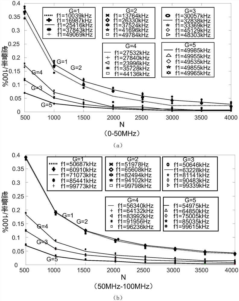
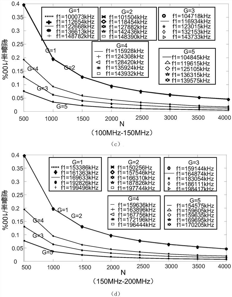
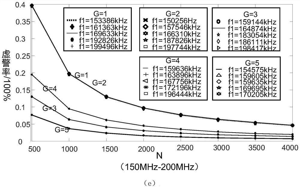

Image

  • A Method of Optical Undersampling Frequency Recovery Based on Remainder Matching
  • A Method of Optical Undersampling Frequency Recovery Based on Remainder Matching
  • A Method of Optical Undersampling Frequency Recovery Based on Remainder Matching

Examples


Embodiment 1

[0128] The validity of the method of the present invention is verified by MATLAB simulation. The electric field sensor system adopts the repetition frequency as f 1 = 213226kHz and f 2 = 216495kHz femtosecond pulse light source. Calculated and analyzed according to the method of the present invention, the frequency application range is the least common multiple of the two repetition frequencies, and its value is 46162362870kHz. When the blur radius is R=50kHz and the measuring frequency range is 10GHz, the false alarm rate of the system is about 4.42%.

[0129] Randomly select 100,000 frequency points in the 10GHz range, and obtain 8951 false alarm excitation frequency points through MATLAB simulation, with a false alarm rate of 4.02%. After removing the false alarm points, the system simulation error is as follows: Figure 5 As shown, the calculation error is less than 50kHz. The simulation results are consistent with the calculation results.

Embodiment 2

[0131] The schematic diagram of the experimental hardware connection is as follows: Figure 6 As shown, the measurement system includes a pulsed light source, an optical switch, an optical circulator, a polarization-maintaining fiber, an optical electric field probe, an optical detector, a spectrum analyzer, and a PC. Although the experiments were performed indoors, neither pulsed light source was finely controlled, consistent with field conditions.

[0132] The signal source injects the radio frequency signal into the GTEM cell (gigahertz TEM cell) through the transmission line, forming a local uniform electric field in the unit; the electric field probe is placed in the static area of ​​the GTEM cell, and is connected to the No. 2 port of the circulator through a long optical fiber; the circulator's Port 1 is connected to two femtosecond pulse light sources through an optical switch controlled by a single-chip microcomputer, port 3 is connected to a photodetector, and the ou...


PUM


Abstract

The invention discloses an optical under-sampling frequency recovery method based on remainder matching. By studying the characteristics of the remainder of the frequency to be measured, the relationship between the repetition frequency, the maximum value of the frequency to be measured, the receiver measurement error and the system error rate is summarized. And design the frequency calculation program. The algorithm of the present invention has universal applicability to the size of the under-sampling repetition frequency difference, not only can be applied to the situation of small repetition frequency difference accurately controlled in the laboratory, but also can be applied to the situation of large repetition frequency difference of fixed-frequency light source. The rapid measurement of field electric field is of great significance.

Description

technical field [0001] The invention belongs to the technical field of broadband fast electric field detection, and in particular relates to a frequency recovery method of a dual pulse light source optical undersampling electric field measurement system based on remainder matching. Background technique [0002] With the development of modern electronic technology, the spectrum components of electromagnetic signals are complex, the frequency bands are widely distributed, and the energy of various signals varies greatly. It is necessary for the electric field measurement system to quickly obtain the spectrum of all possible threats. This requires the measurement system to have the characteristics of high real-time bandwidth, high dynamic range, and high damage resistance threshold. The traditional electric field test system is generally composed of an antenna or a metal probe followed by a receiver. This detection form has high sensitivity, versatility and relatively low cost,...

Claims


Application Information

Patent Timeline
Patent Type & Authority Patents(China)
IPC IPC(8): G01R29/12G01R23/02
CPCG01R29/12G01R23/02
Inventor 谢树果杨燕王天恒田雨墨王铁凝
Owner BEIHANG UNIV
Learn More