
Test system and method

A test system and test device technology, applied in the direction of test/monitoring control system, general control system, electrical test/monitoring, etc., can solve the problems of high cost of testing equipment, inaccurate test results, inconvenient use, etc., and achieve simple wiring, Reduced weight and ease of use

Active Publication Date: 2021-07-13
北京天能继保电力科技有限公司
View PDF12 Cites 0 Cited by
  • Summary
  • Abstract
  • Description
  • Claims
  • Application Information

AI Technical Summary

Problems solved by technology

For the detection of the functional performance of protection measurement and control devices and power distribution automation terminals, there are some deficiencies in the existing testing technology. The detection of the function of the measurement and control device requires a relay protection tester, and two sets of testing equipment are required for the functional performance testing of a device, and the cost of the testing equipment is high; in order to ensure the accuracy of the test results, a high-precision wave recording device must be equipped with a wave recording device during the test , high cost
If you do not configure a high-precision wave recording device or configure an ordinary wave recording device, when there is an objection to the test result, it is impossible to determine whether it is a problem with the testing equipment or the product under test, and the test result may be inaccurate

Method used


Image

  • Test system and method
  • Test system and method
  • Test system and method

Examples


Embodiment Construction

[0062] The principles and features of the present invention will be described below in conjunction with the accompanying drawings, and the examples given are only used to explain the present invention, and are not intended to limit the scope of the present invention.

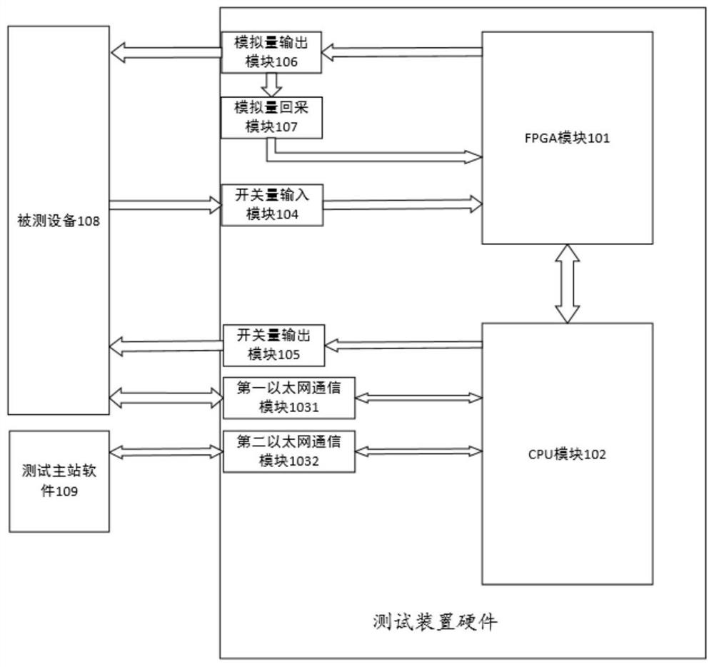
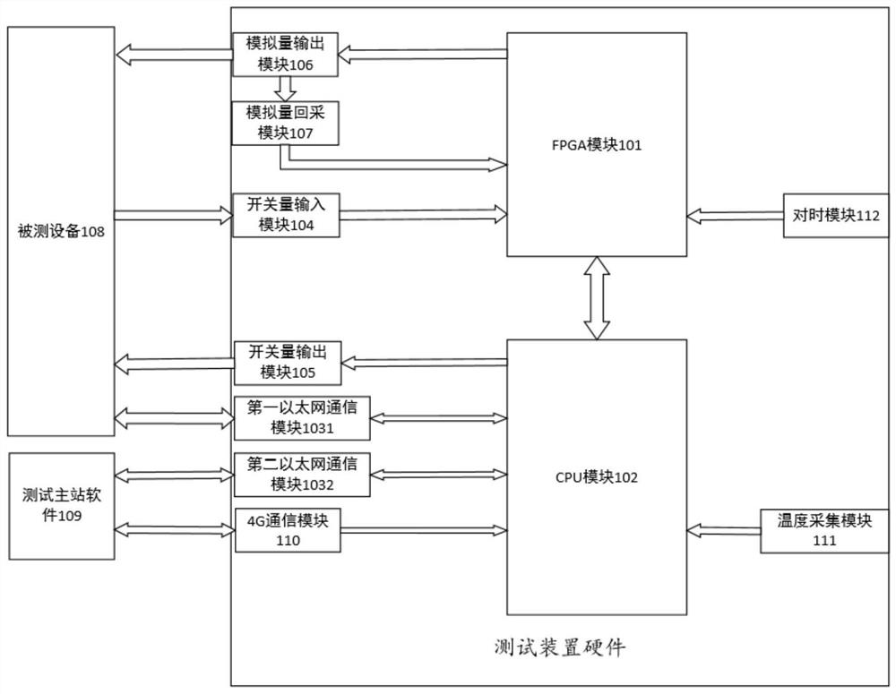
[0063] like figure 1 As shown, a test system provided by an embodiment of the present invention includes: test master station software 109 and test device hardware;

[0064] The test device hardware specifically includes: Ethernet communication module group, analog output module 106, analog output module 107, switch input module 104, switch output module 105, CPU module 102 and FPGA module 101; wherein, the Ethernet communication module The group includes: a first Ethernet communication module 1031 and a second Ethernet communication module 1032;

[0065] FPGA module 101 is connected with analog quantity output module 106, analog quantity recovery module 107, switch quantity input module 104 and CPU module 102 ...


PUM


Abstract

The invention discloses a test system and method, and relates to the field of power system secondary device testing. The system comprises test master station software and test device hardware. The test device hardware specifically comprises an Ethernet communication module group, an analog quantity output module, an analog quantity recovery module, a switching value input module, a switching value output module, a CPU module and an FPGA module. The analog quantity output precision is improved through the analog quantity recovery module, the precision of an alternating current standard current source is achieved, the function of a standard meter is achieved, the measurement function of a protection measurement and control device can be detected, and the alternating current standard current source and the standard meter do not need to be additionally arranged; according to the test device, the protection and measurement function performance of the protection measurement and control device and the function performance of the power distribution automation terminal are detected. High-precision source output, high-precision wave recording and high-precision meter monitoring are provided, system wiring is simplified, the manufacturing cost is reduced, and use is convenient.

Description

technical field [0001] The invention relates to the field of testing secondary devices in electric power systems, in particular to a testing system and method. Background technique [0002] With the improvement of power users' requirements for product quality and the strengthening of the quality control of equipment put into power grid operation, distribution automation terminal products need to undergo type test testing, network access professional testing, sampling testing, and arrival testing. Protection measurement and control devices need to go through type inspection, professional network inspection, and on-site inspection. On-site inspection is routine maintenance inspection, which is divided into acceptance inspection of newly installed devices, regular inspection and supplementary inspection of devices in operation. In addition, manufacturers have to do ex-factory inspections on products. [0003] At present, the detection of the functional performance of the prote...

Claims


Application Information

Patent Timeline
IPC IPC(8): G05B23/02
CPCG05B23/0256G05B2219/24065
Inventor 陈成李春久庄乾鑫韩峰张发俊刘芬杨秀英翟永成
Owner 北京天能继保电力科技有限公司
Learn More