
Heat dissipation mechanism for 3D printer spray head

A technology of 3D printers and heat dissipation mechanisms, applied in the direction of processing heating elements, manufacturing auxiliary devices, coating devices, etc., can solve the problems of unstable heat insulation effect of nozzles, general heat dissipation effect, and reduced printing efficiency, so as to improve printing efficiency , saving printing materials and improving efficiency

Active Publication Date: 2021-07-13
XIAMEN RONGTA TECH
View PDF9 Cites 0 Cited by
  • Summary
  • Abstract
  • Description
  • Claims
  • Application Information

AI Technical Summary

Problems solved by technology

[0003] However, if the heat dissipation fan is directly installed on the heat dissipation aluminum sheet, this structure is likely to cause the overall vibration of the nozzle under the vibration of the heat dissipation fan, which will affect the printing; at the same time, the structure of this structure The heat insulation effect of the nozzle of the 3D printer is not stable, and only the heat dissipation fan is used to dissipate heat from the feed pipe. Blockage will not only cause waste of printing materials, but also reduce printing efficiency

Method used


Image

  • Heat dissipation mechanism for 3D printer spray head
  • Heat dissipation mechanism for 3D printer spray head
  • Heat dissipation mechanism for 3D printer spray head

Examples


Embodiment Construction

[0034] The following will clearly and completely describe the technical solutions in the embodiments of the present invention with reference to the accompanying drawings in the embodiments of the present invention. Obviously, the described embodiments are only some, not all, embodiments of the present invention. Based on the embodiments of the present invention, all other embodiments obtained by persons of ordinary skill in the art without creative efforts fall within the protection scope of the present invention.

[0035] In describing the present invention, it is to be understood that the terms "opening", "upper", "lower", "thickness", "top", "middle", "length", "inner", "surrounding" etc. Indicating orientation or positional relationship is only for the convenience of describing the present invention and simplifying the description, and does not indicate or imply that the components or elements referred to must have a specific orientation, be constructed and operated in a sp...


PUM


Abstract

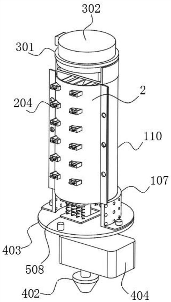
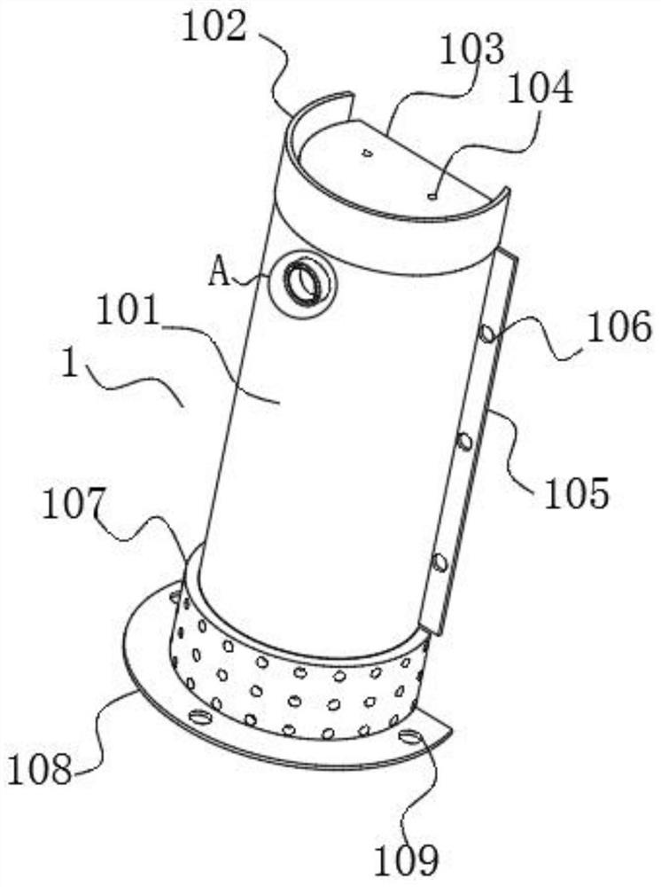
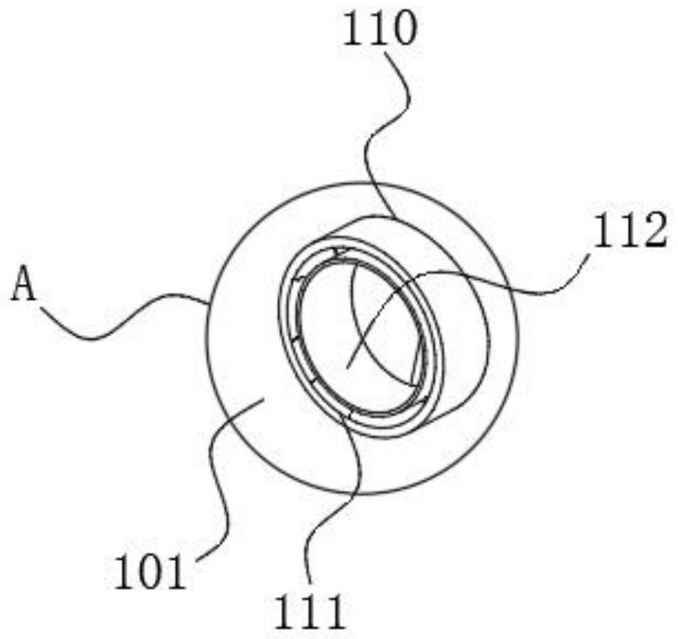
The invention discloses a heat dissipation mechanism for a 3D printer spray head, and relates to the technical field of 3D printers. The heat dissipation mechanism comprises a heat insulation barrel assembly, a mounting face plate, a refrigeration suite and a spray head unit; the refrigeration suite and the heat insulation barrel assembly are in threaded rotation, and the spray head unit is matched with the heat insulation barrel assembly in a sleeving mode; and condensation assemblies are matched with insertion holes in an inserted mode, volute-shaped water pipes are fixedly connected between wave-shaped water pipes, the other ends of the wave-shaped water pipes are fixedly connected with water storage tanks; and micro water pumps are arranged inside the water storage tanks. According to the heat dissipation mechanism for the 3D printer spray head, the spray head unit is arranged in the heat insulation barrel assembly, the refrigeration suite is started, and heat exchange is carried out on the interior of a heat insulation barrel through the condensation assemblies, so that a low-temperature environment is kept inside the heat insulation barrel, and the situation that blockage is caused due to the fact that printing materials start to be softened on the upper portion of an L-shaped feeding pipe due to the fact that the feeding pipe is heated due to long-time heating of a heater is avoided, the printing materials are saved, and the printing efficiency is improved; and after printing is finished, water collecting boxes are pulled out from the mounting face plate, and condensate water is poured out.

Description

technical field [0001] The invention belongs to the technical field of 3D printers, in particular to a cooling mechanism for nozzles of 3D printers. Background technique [0002] 3D printer, a machine of rapid prototyping technology, is a technology based on a digital model file, using bondable materials such as special wax, powdered metal or plastic, to construct objects by layer-by-layer printing. It is often used in mold manufacturing, industrial design and other fields to make models or for direct manufacturing of some products, which means that this technology is becoming popular. The working principle of 3D printers is basically the same as that of ordinary printers. It is to superimpose "printing materials" layer by layer through computer control, and finally turn the blueprint on the computer into a real object; most of the nozzles of 3D printers currently on the market use The nozzle is connected to the heating aluminum block. The aluminum block is equipped with a ...

Claims


Application Information

Patent Timeline
IPC IPC(8): B29C64/20B29C64/209B29C64/295B29C64/30
CPCB29C64/20B29C64/209B29C64/295B29C64/30B33Y30/00B33Y40/00
Inventor 朱凯旋
Owner XIAMEN RONGTA TECH
Learn More