Three-axis welding strip cutter and implementation method thereof

A cutting tool and shaft welding technology, which is applied to cutting tools, manufacturing tools, and accessories of shearing machines, etc., can solve the problem of inconvenient realization of multiple sets of welding strip handling structures, unfavorable handling layout, and multiple sets of welding strips. The problem that the cutting and pulling lines cannot be carried out can achieve the effect of good cutting effect, improved efficiency and convenient cutting.

Active Publication Date: 2021-07-13
HANGZHOU JOY ENERGY TECH CO LTD
View PDF6 Cites 3 Cited by
  • Summary
  • Abstract
  • Description
  • Claims
  • Application Information

AI Technical Summary

Problems solved by technology

[0005] The design of the multi-set welding strip handling structure for the above traditional welding strip cutting is not convenient to realize on this structure; and the width of the upper cutting knife is too wide to temporarily occupy a large part of the space, which is not conducive to the layout of the handling; for multiple sets of welding strips The technical problem that the cutting wire cannot be carried out, the invention provides a three-axis welding ribbon cutter and its implementation method. The knife can move in three axes to realize automatic multi-group cutting, which greatly improves the cutting efficiency, and can protect the welding strip, improve the cutting effect, and has high safety

Method used


Image

  • Three-axis welding strip cutter and implementation method thereof
  • Three-axis welding strip cutter and implementation method thereof
  • Three-axis welding strip cutter and implementation method thereof

Examples


Embodiment

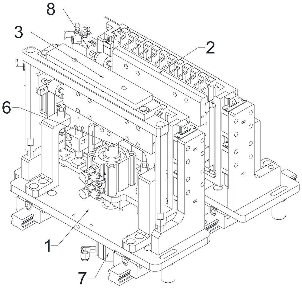
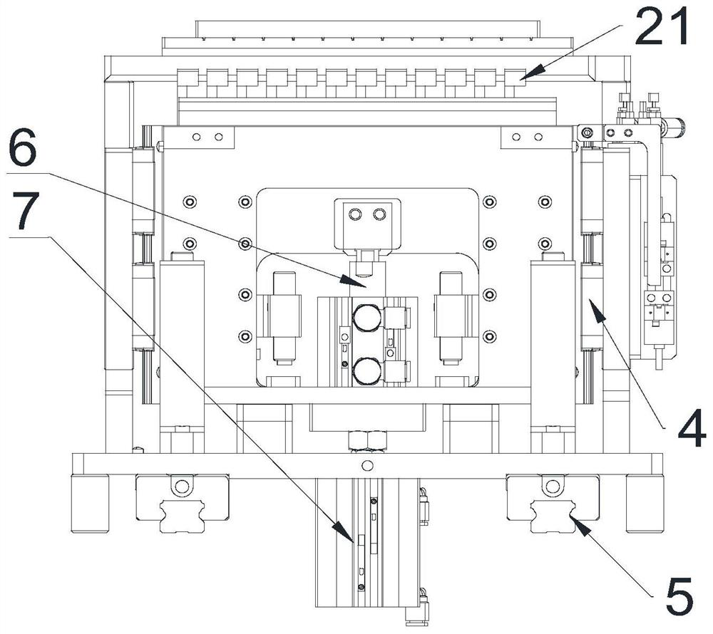
[0035] combined with Figure 1-4 , a three-axis welding ribbon tool, including a base 1, a traverse knife group 2, a wire mechanism 3, a first guide rail 4, a second guide rail 5, a cutting cylinder 6, a lifting cylinder 7, a traverse cylinder 8 and a solder ribbon 9. The base 1 is provided with a mounting block, and the mounting block is connected with other components through a bolt structure or a rivet structure.

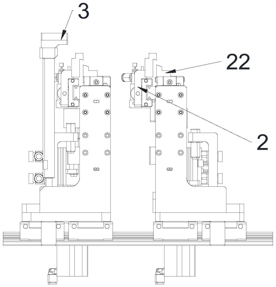
[0036] The mounting block is fixedly connected with a traverse knife group 2, a wire mechanism 3, a first guide rail 4, a second guide rail 5, a cutting cylinder 6, a lifting cylinder 7 and a traverse cylinder 8, and the cutters of the traverse knife group 2 Multiple groups are provided with the wire mechanism 3, and the through holes matching the number of special-shaped cutters 21 are arranged on the wire mechanism 3. The through hole is used for passing the first-level limiting welding strip 9 .

[0037] The traverse knife group 2 includes a special-shaped c...


PUM


Abstract

The invention discloses a three-axis welding strip cutter and an implementation method thereof, and relates to the technical field of welding strip cutting. The three-axis welding strip cutter comprises a base, a transverse moving cutter set, wire guiding mechanisms, a first guide rail, a second guide rail, a cutting air cylinder, a lifting air cylinder, a transverse moving air cylinder and a welding strip, the base is provided with a mounting block, the mounting block is fixedly connected with the transverse moving cutter set, multiple sets of wire guiding mechanisms, the first guide rail, the cutting air cylinder, the lifting air cylinder and the transverse moving air cylinder, the transverse moving cutter set comprises multiple sets of cutters, the transverse moving cutter set comprises a special-shaped cutter, the special-shaped cutter is connected to the cutting air cylinder and the transverse moving air cylinder, and the cutter point of the special-shaped cutter extends by a certain volume. The transverse moving cutter set and a lower cutter are both connected to the lifting air cylinder. The three-axis welding strip cutter and the implementation method thereof have the following advantages that (1) the welding strip cutting efficiency is improved; (2) the cutting effect of a welding strip is good; (3) welding strip cutting is facilitated; and (4) the cutters are in a low position when not working and are far away from an operator, so that the safety is high.

Description

technical field [0001] The invention relates to the technical field of ribbon cutting, in particular to a three-axis ribbon cutter and an implementation method thereof. Background technique [0002] Photovoltaic soldering strips, also known as tinned copper strips or tinned copper strips, are divided into confluence strips and interconnection strips, which are used in the connection between photovoltaic module cells and play an important role in conducting electricity and gathering electricity. Ribbon is an important raw material in the welding process of photovoltaic modules. The quality of the ribbon will directly affect the current collection efficiency of photovoltaic modules and greatly affect the power of photovoltaic modules. Due to the physical characteristics of the welding strip, its cutting process requires certain technical requirements. [0003] The traditional welding ribbon cutting is generally combined with the upper and lower cutters, but the upper cutter i...

Claims


Application Information

Patent Timeline
Patent Type & Authority Applications(China)
IPC IPC(8): B23D15/02B23D15/14B23D33/02B23D35/00
CPCB23D15/02B23D15/14B23D33/02B23D35/00B26D1/045B26D2001/0053B26D2001/0066
Inventor 张建党张治雨
Owner HANGZHOU JOY ENERGY TECH CO LTD
Why Eureka
Try Eureka