Automatic magnetic material production line structure

An automatic production line and magnetic material technology, applied in chemical instruments and methods, solid separation, separating solids from solids with airflow, etc., can solve the problems of delay in screening progress, blockage of sieve plate sieve holes, long time required, etc.

Active Publication Date: 2021-07-06
ZAOZHUANG UNIV
View PDF12 Cites 0 Cited by
  • Summary
  • Abstract
  • Description
  • Claims
  • Application Information

AI Technical Summary

Problems solved by technology

[0004] Based on the existing magnetic materials processing process, the crushed magnetic materials need to be screened through the screening device. In the screening process of the existing screening equipment, the magnetic materials are generally screened by the vibrating motor to drive the sieve plate. During the screenin

Method used


Image

  • Automatic magnetic material production line structure
  • Automatic magnetic material production line structure
  • Automatic magnetic material production line structure

Examples


Embodiment 1

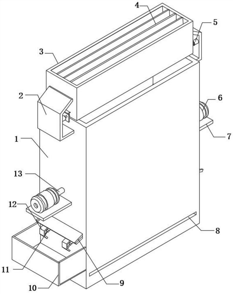
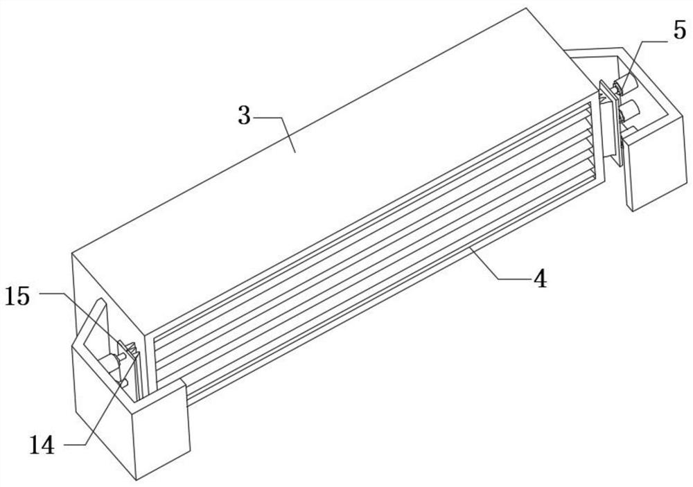
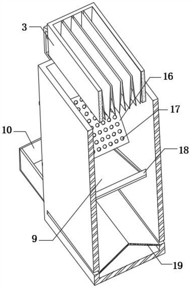
[0025] refer to Figure 1-3 , a magnetic material automatic production line structure, comprising a screen box 1, the inner walls of both sides of the screen box 1 are fixedly connected with blowing plates 16, and the top outer walls of the two blowing plates 16 are provided with blowing holes 17 at equal distances, the two The four blowing plates 16 are arranged in eight rows, and the outer walls of the two sides of the screen box 1 near the two blowing plates 16 are fixedly connected with mounting plates 7, and the top outer walls of the two mounting plates 7 are fixedly connected with blowers 6, and the two The air blowing end of each air blower 16 is all fixedly connected with air delivery pipe 13, and the other end of air delivery pipe 13 is fixedly connected in the inside of blast plate 16, and the bottom inwall of screen box 1 is fixedly connected with tapered material distribution plate 19, and the screen box 1 There are feeding holes 8 on both sides of the outer walls...

Embodiment 2

[0034] refer to Figure 1-4, a magnetic material automatic production line structure, comprising a screen box 1, the inner walls of both sides of the screen box 1 are fixedly connected with blowing plates 16, and the top outer walls of the two blowing plates 16 are provided with blowing holes 17 at equal distances, the two The four blowing plates 16 are arranged in eight rows, and the outer walls of the two sides of the screen box 1 near the two blowing plates 16 are fixedly connected with mounting plates 7, and the top outer walls of the two mounting plates 7 are fixedly connected with blowers 6, and the two The air blowing end of each air blower 16 is all fixedly connected with air delivery pipe 13, and the other end of air delivery pipe 13 is fixedly connected in the inside of blast plate 16, and the bottom inwall of screen box 1 is fixedly connected with tapered material distribution plate 19, and the screen box 1 There are feeding holes 8 on both sides of the outer wall n...


PUM


Abstract

The invention belongs to the technical field of magnetic material processing, and particularly relates to an automatic magnetic material production line structure which comprises a screen box, air blowing plates are fixedly connected to the inner walls of the two sides of the screen box, air blowing holes are formed in the outer walls of the tops of the two air blowing plates at equal intervals, and the two air blowing plates are arranged in an inverted eight-shaped mode. Mounting plates are fixedly connected to the outer walls of the two sides, close to the two air blowing plates, of the screen box, air blowers are fixedly connected to the outer walls of the tops of the two mounting plates, and air conveying pipes are fixedly connected to the air blowing ends of the two air blowers. According to the automatic magnetic material production line structure, discharging plates, hydraulic cylinders, adjusting plates and vibration blocks are arranged, and when magnetic materials are discharged, the hydraulic cylinders are started to drive the vibration blocks on the adjusting plates to repeatedly impact a discharging frame, so that the magnetic materials can smoothly fall through gaps between the discharging plates, the discharging speed is increased, and meanwhile, during discharging, the magnetic materials are equally divided through the discharging plates, and the subsequent screening effect is improved.

Description

technical field [0001] The invention relates to the technical field of magnetic material processing, in particular to an automatic production line structure for magnetic materials. Background technique [0002] Magnetic materials, magnetic materials refer to substances that can directly or indirectly generate magnetism from transition elements such as iron, cobalt, nickel and their alloys; magnetic materials can be divided into soft magnetic materials and hard magnetic materials according to the difficulty of demagnetization after magnetization; magnetization The material that is easy to demagnetize is called soft magnetic material, and the material that is not easy to demagnetize is called hard magnetic material; generally speaking, the remanence of soft magnetic material is small, and the remanence of hard magnetic material is large; It is batched, crushed, pressed and sintered. After crushing, it needs to be screened by a screening device. [0003] In the existing magnet...

Claims


Application Information

Patent Timeline
IPC IPC(8): B07B7/01B07B11/06B07B11/02
CPCB07B7/01B07B11/06B07B11/02
Inventor 杨中国蔡田芳孙正李威缑亚楠张业伟李辉李垒
Owner ZAOZHUANG UNIV
Why Eureka
Try Eureka