
Multi-stage compression refrigeration device

A compression refrigeration and refrigerant technology, used in refrigerators, compressors, refrigeration components, etc., can solve the problems of small refrigeration capacity and low refrigeration efficiency, and achieve the effect of reducing noise and easy control.

Active Publication Date: 2021-07-02
LG ELECTRONICS INC
View PDF6 Cites 0 Cited by
  • Summary
  • Abstract
  • Description
  • Claims
  • Application Information

AI Technical Summary

Problems solved by technology

In the case of using only the inlet guide vane to control the refrigeration unit, the reduction in refrigeration efficiency is the least compared with other methods, but since the reduction in refrigeration capacity is not large, there is a problem that it is difficult to maintain a small value of refrigeration capacity. The problem of dealing with the low load operation of the
[0009] When the load control of the refrigeration device cannot be carried out only with the inlet guide vane, the refrigerant in the condenser will be directly transferred to the evaporator through the bypass of high-temperature gas. In this case, there will be a problem that the cooling efficiency will be greatly reduced

Method used


Image

  • Multi-stage compression refrigeration device
  • Multi-stage compression refrigeration device
  • Multi-stage compression refrigeration device

Examples


Embodiment Construction

[0068] The aforementioned objects, features, and advantages will be described in detail with reference to the accompanying drawings, so that those skilled in the art can easily implement the technical idea of ​​the present invention. During the description of the present invention, when it is judged that the detailed description of the known technology related to the present invention obscures the gist of the present invention, the detailed description thereof will be omitted. Hereinafter, preferred embodiments of the present invention will be described in detail with reference to the accompanying drawings. In the drawings, the same reference numerals denote the same or similar structural elements.

[0069] Although constituent elements such as first, second, etc. are used in order to describe a plurality of structural elements, these constituent elements are not limited to these terms. These terms are used only to distinguish one constituent element from another constituent ...


PUM


Abstract

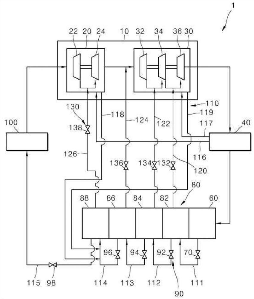
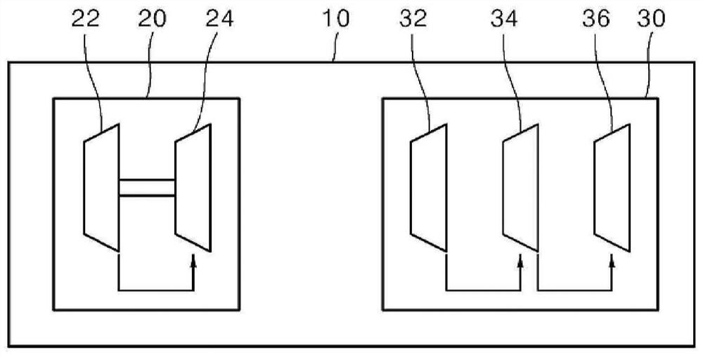
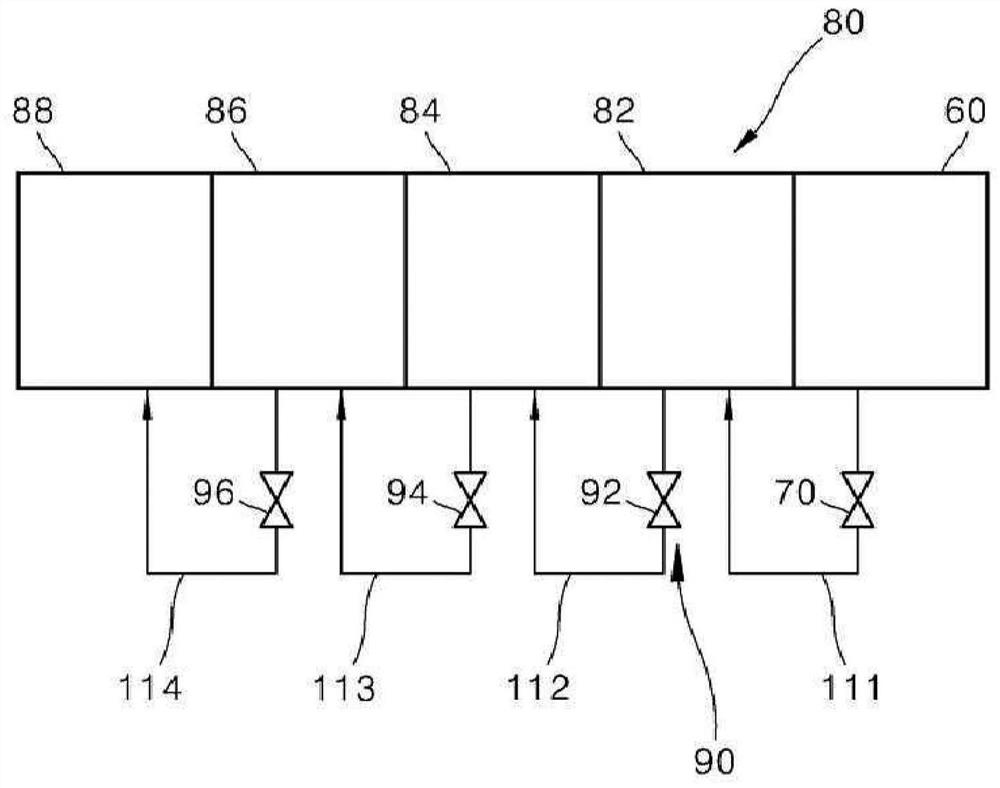
The invention discloses a multi-stage compression refrigeration device. The multi-stage compression refrigeration device of the present invention includes: a compression part, which compresses refrigerant at a plurality of compression ends; a condensation part, connected to the compression part, wherein the refrigerant passing through the compression part is condensed through heat exchange; a liquid storage device which is connected to the condensation part and stores a condensed liquid refrigerant in the condensation part; a first expansion valve part which is arranged in the pipe connected to the liquid storage device and expands the refrigerant discharged from the liquid storage device; a gas-liquid separation part, which receives the refrigerant passing through the first expansion valve part and separates the refrigerant into a liquid refrigerant and a gaseous refrigerant, and supplies the gaseous refrigerant to the compression part; a second expansion valve part which is arranged in a pipe connected to the gas-liquid separation part and expands the refrigerant discharged from the gas-liquid separation part; and an evaporating part which is connected to the gas-liquid separation part and the compression part, and converts the liquid refrigerant discharged from the gas-liquid separation part into a gaseous refrigerant through heat exchange. The gas-liquid separation part may be provided downstream of the liquid storage part.

Description

technical field [0001] The invention relates to a multi-stage compression refrigeration device. Background technique [0002] As a general refrigeration device, a refrigerator (Chiller) can be used. A chiller is a large refrigeration system that provides refrigeration to large buildings and uses cold water or antifreeze as a refrigerant to transfer matter as a heat source. [0003] Chillers are devices that deliver cold water to where it is needed. In addition, the chiller conducts heat exchange between refrigerant circulating in the refrigerant cycle and cold water circulating at demand, thereby cooling the cold water. A refrigeration unit using a refrigerator is a large-capacity facility, so it can be installed in a large-scale building, etc. [0004] The cold water cooled by the refrigeration unit using the refrigerator is supplied to the place where the demand is used such as the air conditioner. [0005] The refrigerator unit includes: a compressor for compressing r...

Claims


Application Information

Patent Timeline
Patent Type & Authority Applications(China)
IPC IPC(8): F25B1/10F25B41/325F25B41/40F25B41/20F25B43/00
CPCF25B1/10F25B43/006F25B2600/25F25B49/02F25B41/20F25B43/043F25B2600/022
Inventor 金完祚金奎英郭民熙朴相云
Owner LG ELECTRONICS INC
Learn More