
A jig and method for laser cutting of aerospace titanium alloy

A technology of laser cutting and laser cutting head, which is applied in the field of parts processing, can solve the problems that the assembled cutting fixture does not have a fixed function, the laser cutting head collides with the part, the cutting fixture, affects the production progress and delivery cycle of the part, and shortens the delivery cycle, ensure processing quality, save the effect of grinding process

Active Publication Date: 2021-10-08
CHENGDU AIRCRAFT INDUSTRY GROUP
View PDF16 Cites 0 Cited by
  • Summary
  • Abstract
  • Description
  • Claims
  • Application Information

AI Technical Summary

Problems solved by technology

[0003] 1. Part of the assembled cutting fixture does not have the function of being fixed to the bottom of the machine tool. When the position of the part changes due to special circumstances, the positioning of the part will be inaccurate;
[0004] 2. The part where the simple assembly fixture is in contact with the part rubs against each other due to manufacturing accuracy and surface roughness, resulting in poor surface quality of the part. After cutting the part, it needs to be polished to affect the production progress and delivery cycle of the part;
[0005] 3. The laser cutting CNC program has not been simulated before the cutting process, and overtravel problems are prone to occur during the cutting process, and what is more, there will be safety accidents such as the laser cutting head colliding with parts and cutting fixtures;
[0006] 4. Since most titanium alloy parts are formed by hot pressing die extrusion at high temperature, the forming accuracy of titanium alloy is related to the precision of the mold, the degree of molding and the shrinkage of the parts after cooling, and the parts of the parts are easy to identify There are deviations between the characteristic points and the digital model, so the machining accuracy of the parts using the traditional positioning method is not high, and it is necessary to modify the program many times or change the coordinate reference for closed-light trial cutting;
[0007] 5. Due to the deviation between the easily identifiable local feature points of the part and the digital model, using the local feature points of the part as the coordinate system direction point of NC programming has the disadvantage of large processing errors

Method used


Image

  • A jig and method for laser cutting of aerospace titanium alloy
  • A jig and method for laser cutting of aerospace titanium alloy
  • A jig and method for laser cutting of aerospace titanium alloy

Examples


Embodiment 1

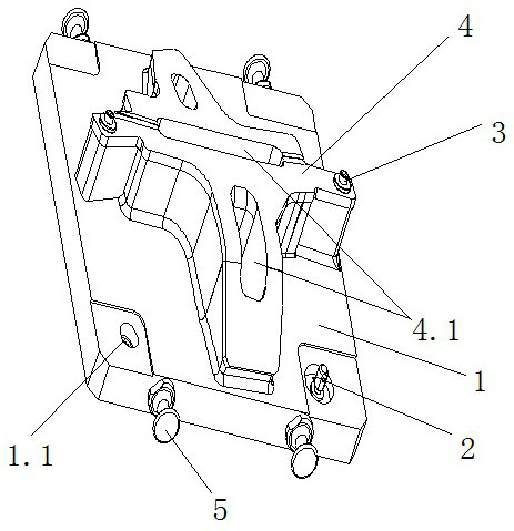
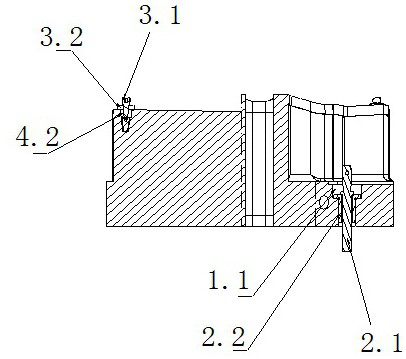
[0057] This embodiment discloses a kind of aerospace titanium alloy laser cutting fixture, as a kind of basic embodiment of the present invention, such as figure 1 The schematic diagram of the overall structure of the cutting fixture is shown, including a base plate base 1, at least two clamp positioning parts 2 and at least two part positioning parts 3; the base plate base 1 is provided with clamps corresponding to the clamp positioning parts 2 one by one The positioning hole 1.1, the top of the bottom plate base 1 is provided with a profile protrusion 4 for supporting titanium alloy parts, and the profile protrusion 4 is provided with a part positioning hole 4.2 corresponding to the part positioning part 3 one-to-one.

[0058] In the actual production of this technical solution, based on the simple composition structure of the cutting jig, cast aluminum can be used as the manufacturing material of the cutting jig. In this way, the cutting jig is lighter in weight and has bett...

Embodiment 2

[0060] This example discloses an aviation titanium alloy laser cutting jig, as a preferred embodiment of the present invention, that is, in Example 1, since the titanium alloy parts are generally large parts, the cutting jigs needed are generally larger in size , Therefore, the aforementioned "light weight of the jig" is only relative to ordinary jigs (such as the simple splicing jigs in the prior art) or cutting jigs made of other materials. Aside from these comparisons, the weight of the cutting jig itself is relatively It is heavy, and it is troublesome to carry it by hand. Therefore, it is necessary to use a crane for auxiliary transportation. In order to increase the focus of transportation, four lifting rings 5 ​​are arranged on the base plate base 1, and the four lifting rings 5 ​​are evenly distributed on the base plate base. Both sides of the seat 1 are arranged in a rectangular structure as a whole. During use, use a crane to hang four nylon belt hooks, hang the hook...

Embodiment 3

[0062] This example discloses an aviation titanium alloy laser cutting jig, as a preferred embodiment of the present invention, that is, in Example 1, since the titanium alloy parts are generally large parts, the cutting jigs needed are generally larger in size , Therefore, the aforementioned "light weight of the jig" is only relative to ordinary jigs (such as the simple splicing jigs in the prior art) or cutting jigs made of other materials. Aside from these comparisons, the weight of the cutting jig itself is relatively Heavy, therefore, a hollow structure 4.1 is provided in the middle region of the profile protrusion 4 . The setting of the hollow structure 4.1 can save the use of some materials, reduce the cost of materials and make the cutting jig more portable under the condition that the titanium alloy parts are not deformed and concave due to gravity.


PUM

PropertyMeasurementUnit
hardnessaaaaaaaaaa

Abstract

The invention belongs to the technical field of parts processing, and in particular relates to a jig and method for laser cutting of aviation titanium alloys, comprising a bottom plate base, at least two fixture positioning parts and at least two part positioning parts; the bottom plate base is provided with a jig and The positioning parts correspond to the fixture positioning holes one by one, and the top of the bottom plate base is provided with profile protrusions for supporting titanium alloy parts, and the profile protrusions are provided with part positioning holes corresponding to the part positioning parts one-to-one. This technical solution can be based on the simple composition structure of the cutting jig, and adopts cast aluminum as the manufacturing material of the cutting jig, which makes the cutting jig lighter in weight and better in strength and fatigue limit; After grinding, it can have a smooth surface structure. Under the conditions of supporting the titanium alloy plate, the convex surface of the profile will not be deformed, and it can also effectively avoid surface quality problems such as scratches on the surface of titanium alloy parts.

Description

technical field [0001] The invention belongs to the technical field of part processing, and in particular relates to an aviation titanium alloy laser cutting jig and a method. Background technique [0002] At present, most of the laser cutting of titanium alloys use simple assembly fixtures to clamp the parts. Since the simple assembly fixture does not have a more accurate positioning module and there is no three-dimensional digital model, the positioning coordinate system of laser cutting CNC programming mainly uses the feature points of the titanium alloy digital model for positioning. This positioning method has the following defects: [0003] 1. Part of the assembled cutting fixture does not have the function of being fixed to the bottom of the machine tool. When the position of the part changes due to special circumstances, the positioning of the part will be inaccurate; [0004] 2. The part where the simple assembly fixture is in contact with the part rubs against eac...

Claims


Application Information

Patent Timeline
Patent Type & Authority Patents(China)
IPC IPC(8): B23K26/70B23K37/04B23K26/38B23K103/14
CPCB23K26/38B23K37/0443B23K26/702B23K2103/14
Inventor 王军李光俊高鹏唐云洪马争胡麒麟
Owner CHENGDU AIRCRAFT INDUSTRY GROUP
Learn More