
LED control method, control device and LED display

A control method and LED lamp technology, applied in energy-saving control technology, static indicators, instruments, etc., can solve problems such as LED light-emitting diode fluctuations, influence on PWM control, abnormal brightness changes, etc., to improve display effects, reduce AC interference, The effect of prolonging Δt

Active Publication Date: 2022-05-17
SUZHOU KEDA TECH
View PDF0 Cites 0 Cited by
  • Summary
  • Abstract
  • Description
  • Claims
  • Application Information

AI Technical Summary

Problems solved by technology

[0008] The above is a typical LED screen PWM control method, but this method has a fatal problem: crosstalk
When the voltage across the LED is on (or off), a short AC signal (Δv / Δt) will be formed between the instantaneous voltage change Δv and the instantaneous time Δt. This AC change will be due to electromagnetic and other reasons. The circuit crosstalks to other LED control circuits, which affects the normal PWM control of other circuits, causing the LED light-emitting diodes on other control circuits to fluctuate unnecessarily, resulting in abnormal changes in brightness
At present, basically all LED screens will have display problems caused by this kind of crosstalk. Since this problem is a pure powerlessness phenomenon, it cannot be eliminated in essence.

Method used


Image

  • LED control method, control device and LED display
  • LED control method, control device and LED display
  • LED control method, control device and LED display

Examples


Embodiment Construction

[0055]In order to make the purpose, technical solutions and advantages of the present invention clearer, the technical solutions in the embodiments of the present invention will be clearly and completely described below in conjunction with the accompanying drawings in the embodiments of the present invention. Obviously, the described embodiments are only Some, but not all, embodiments of the invention. Based on the embodiments of the present invention, all other embodiments obtained by persons of ordinary skill in the art without making creative efforts belong to the protection scope of the present invention.

[0056] As mentioned in the background art, at present, due to various difficulties in accurately controlling the current intensity of LEDs, under the current technical conditions, the brightness control of LED light-emitting diodes is all realized by means of PWM (pulse width modulation). The PWM control method of the LED screen has a fatal problem: crosstalk. When the...


PUM


Abstract

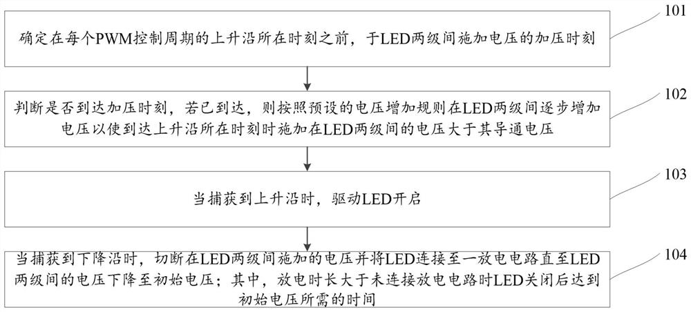
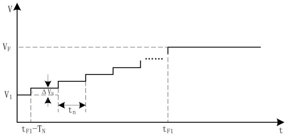
The embodiment of the present application discloses an LED control method, a control device, and an LED display screen. The method includes: determining the time of applying voltage between the two stages of the LED before the rising edge of each PWM control cycle; judging whether it has reached If the pressurization time has been reached, the voltage will be gradually increased between the two stages of the LED according to the preset voltage increase rule so that the voltage applied between the two stages of the LED at the moment of the rising edge is greater than its conduction voltage; when the rising edge is captured edge, drive the LED to turn on; when the falling edge is captured, cut off the voltage applied between the two stages of the LED and connect the LED to a discharge circuit until the voltage between the two stages of the LED drops to the initial voltage; where the discharge time is longer than that of the unconnected The time required to reach the initial voltage after the LED is turned off when discharging the circuit. This application reduces the impact of AC crosstalk on other LED control circuits, greatly simplifies the difficulty of circuit design, improves the display effect of images, and lays the foundation for continuing to increase the number of image bits.

Description

technical field [0001] The invention belongs to the technical field of LED lighting, and in particular relates to an LED control method, a control device and an LED display screen. Background technique [0002] LED (Light-Emitting Diode) screen has become the main way of outdoor display, and with the continuous optimization of pitch size, its fineness is close to traditional display screens such as LCD, so it will gradually become the main screen for indoor display. It can be known from the volt-ampere characteristics of the LED that only when the forward voltage at both ends of the LED light-emitting diode is higher than the conduction voltage V F When, the LED light-emitting diode will emit light, and the intensity of the light will increase with the increase of the current. [0003] However, due to various difficulties in the current technology to accurately control the current intensity, under the current technical conditions, the brightness control of LED light-emittin...

Claims


Application Information

Patent Timeline
Patent Type & Authority Patents(China)
IPC IPC(8): G09G3/32
CPCG09G3/32Y02B20/40
Inventor 白涛周浩梁正曹李军
Owner SUZHOU KEDA TECH
Learn More