Eureka AIR delivers breakthrough ideas for toughest innovation challenges, trusted by R&D personnel around the world.

Non-contact detection device and method for building outer wall surface layer quality

A non-contact, detection device technology, used in measurement devices, mechanical measurement devices, and mechanical devices, etc., can solve the problems of difficult detection, low detection efficiency, and inaccurate data, to ensure stability, improve Efficiency and accuracy, the effect of increased flexibility

Pending Publication Date: 2021-06-29
ZHEJIANG PROVINCE INST OF ARCHITECTURAL DESIGN & RES
View PDF9 Cites 1 Cited by
  • Summary
  • Abstract
  • Description
  • Claims
  • Application Information

AI Technical Summary

Problems solved by technology

Among them, the on-site pull-out test is a destructive test, and the percussion method is limited by the scope of implementation, so it can only be carried out on a part of the building's facade, and its test results cannot fully represent the overall surface quality.
Although conventional hand-held infrared thermal imager shooting and analysis methods can carry out general inspection on the exterior wall surface of buildings, due to the shooting angle, wall heat reflection and other reasons, it is impossible to accurately judge the quality of the exterior wall surface.
At the same time, this method can only qualitatively detect the quality problems of the external wall surface, and cannot quantitatively analyze the hollow drum size, crack length, cold and hot bridge size, and shedding size of the surface layer.
At present, the widely used non-contact measurement is the size measurement technology based on distance measurement and angle measurement, that is, by measuring the distance between the two ends of the target and measuring the angle between the two distance measurements at the same time, the cosine law can be used to obtain The length between the two ends of the target, this method is easy to operate, but due to the poor reproducibility of the measurement results, it is impossible to accurately restore the location of the quality problem of the outer wall surface layer according to the test results, and there are problems in the detection of invisible defects such as hollow drums and cold and heat bridges. very difficult
[0004] In addition, for walls of different heights and widths, the detection efficiency is low, and the collected data is not accurate enough. Therefore, it is urgent to develop a non-contact detection device and method for the quality of the exterior wall surface of a building to solve the problems in the prior art. The problem

Method used


Image

  • Non-contact detection device and method for building outer wall surface layer quality
  • Non-contact detection device and method for building outer wall surface layer quality
  • Non-contact detection device and method for building outer wall surface layer quality

Examples


Embodiment 1

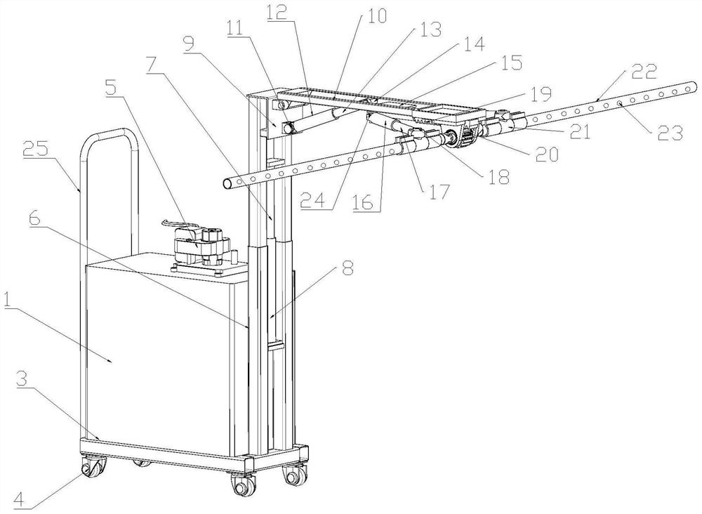
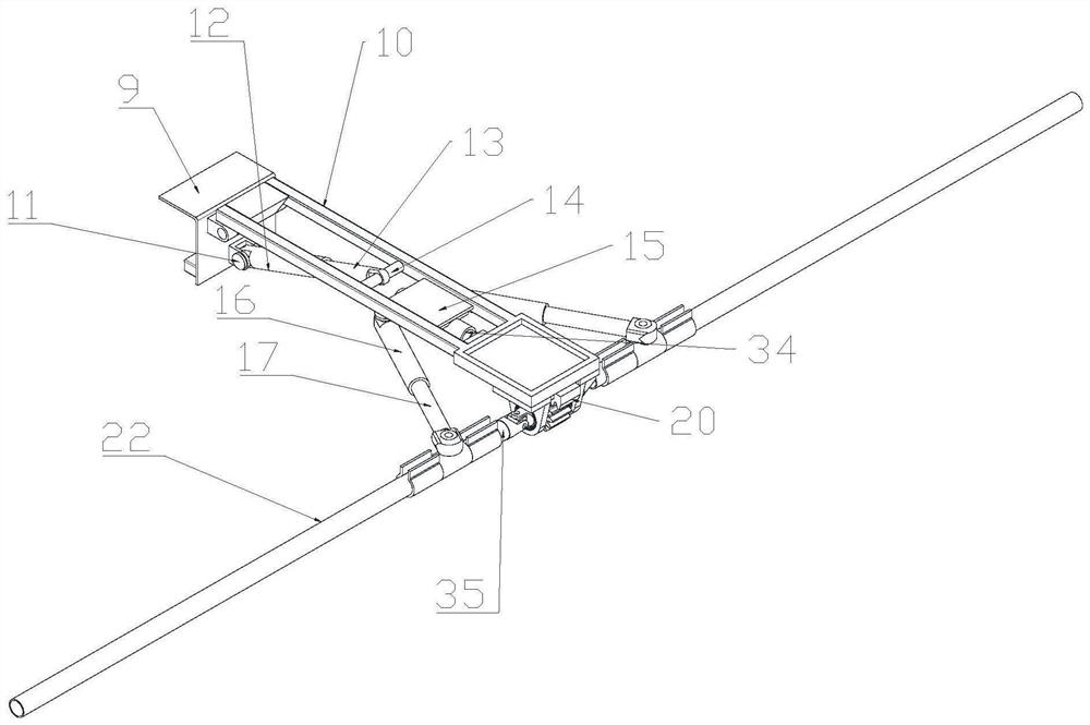
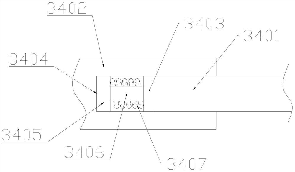
[0037] see Figure 1~4 , in an embodiment of the present invention, a non-contact detection device for the quality of the exterior wall surface layer of a building includes a base 3 and a box body 1 installed on the upper end of the base 3, the upper end of the box body 1 is provided with a handle 2, and the base 3 The lower end of the lower end is provided with several universal wheels 4, and one side of the box body 1 is provided with a first installation frame 6, and one side of the first installation frame 6 is provided with a first hydraulic cylinder 8, and the first hydraulic cylinder 8 The upper end of the cylinder 8 is provided with a first hydraulic rod 7, and a sliding seat 9 is installed on the first hydraulic rod 7. One side of the sliding seat 9 is provided with a second mounting frame 10, and one of the second mounting frame 10 A fixed shaft sleeve 21 is arranged on the side, and a test tube 22 is provided at both ends of the fixed shaft sleeve 21. The side of th...

Embodiment 2

[0048] Such as Figure 5 As shown, the difference between this embodiment and Embodiment 1 is that the lower end of the second mounting frame 10 is provided with a mounting plate 26, and one side of the mounting plate 26 is provided with several fifth rotating shafts 31. The outer periphery of the fifth rotating shaft 31 is provided with a roller shaft 32 , and the outer periphery of the roller shaft 32 is provided with a buffer bushing 33 . By setting the mounting plate 26 at the lower end of the fifth mounting bracket, several fifth rotating shafts 31 are arranged on one side of the mounting plate 26, the outer periphery of the fifth rotating shaft 31 is provided with a roller shaft 32, and the outer periphery of the roller shaft 32 is provided with a buffer sleeve 33, and the roller shaft 32 rotates around the fifth rotating shaft 31, and the setting of the buffer sleeve 33 can ensure the stability of the movement of the test tube 22, thereby effectively ensuring the stabil...


PUM


Abstract

The invention relates to a non-contact detection device for building outer wall surface layer quality. The device comprises a base and a box body mounted at the upper end of the base, a handle is arranged at the upper end of the box body, and a plurality of universal wheels are arranged at the lower end of the base; a first mounting frame is arranged at one side of the box body, and a first hydraulic cylinder is arranged at one side of the first mounting frame; a first hydraulic rod is arranged at the upper end of the first hydraulic cylinder, a sliding seat is mounted on the first hydraulic rod, and a second mounting frame is arranged at one side of the sliding seat; a fixing shaft sleeve is arranged at one side of the second mounting frame, testing pipes are arranged at the two ends of the fixing shaft sleeve, and a plurality of moisture permeable openings are formed in the sides, away from the second mounting frame, of the testing pipes; an installing base is arranged in each testing pipe, an information collection host is arranged at the side, close to a perspective opening, of the mounting base, a camera is arranged at the side, close to the perspective opening, of the information collection host, and a control host electrically connected with the information collection host is arranged at the upper end of the box body. According to the invention, the efficiency and accuracy of wall surface layer quality detection can be effectively improved.

Description

technical field [0001] The invention relates to the technical field of building detection, in particular to a non-contact detection device and method for the quality of a building exterior wall surface layer. Background technique [0002] The surface layer of the building's exterior wall (including the brick finish layer, insulation layer, plastering layer and other structural layers located outside the main body of the building's exterior wall, hereinafter collectively referred to as the surface layer) due to construction quality, material quality, climate conditions, biological erosion, etc. Quality problems such as hollowing, cracking, and cold and heat bridges will occur during use. Such surface layer quality problems will reduce the overall energy-saving effect of the building, and seriously cause the surface layer to fall off, endangering the safety of people's lives and property. Therefore, accurate detection and evaluation of hollowing size, crack length, cold and ho...

Claims


Application Information

Patent Timeline
IPC IPC(8): G01B11/00G01B5/00F16M11/42F16M11/24F16F15/067
CPCG01B11/00G01B5/0002G01B5/0004F16M11/24F16M11/42F16F15/067
Inventor 朱鸿寅钱杰
Owner ZHEJIANG PROVINCE INST OF ARCHITECTURAL DESIGN & RES
Why Eureka
Eureka Blog
Learn More