Superfine fiber production device based on jet spinning method principle
A technology of ultra-fine fiber and production equipment, which is applied in the direction of clustering of newly extruded filaments, melt spinning, fiber processing, etc., and can solve the problem that the ultra-fine fiber cannot be automatically cut, the ultra-fine fiber cannot be automatically transported, and the automatic control cannot be realized Fiber raw material flow and other issues, to achieve the effect of winding superfine fiber effect
- Summary
- Abstract
- Description
- Claims
- Application Information
AI Technical Summary
Problems solved by technology
Method used
Image
Examples
Embodiment 1
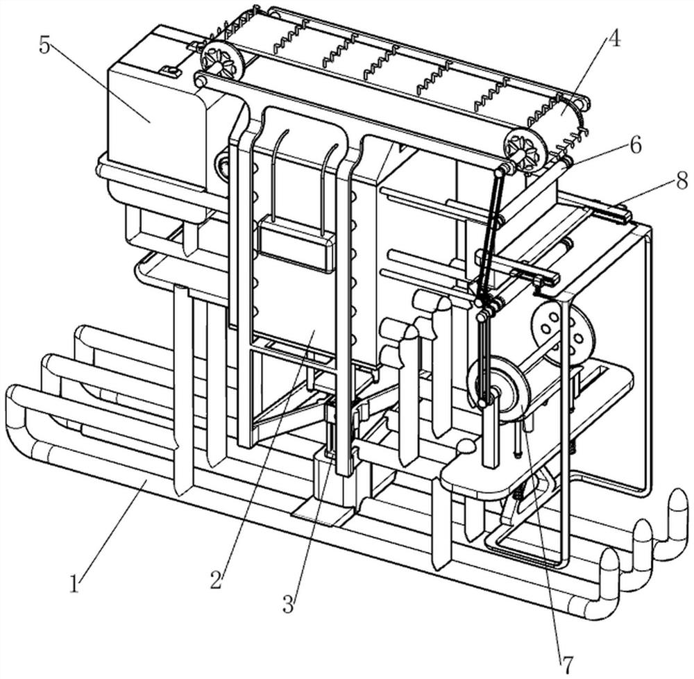
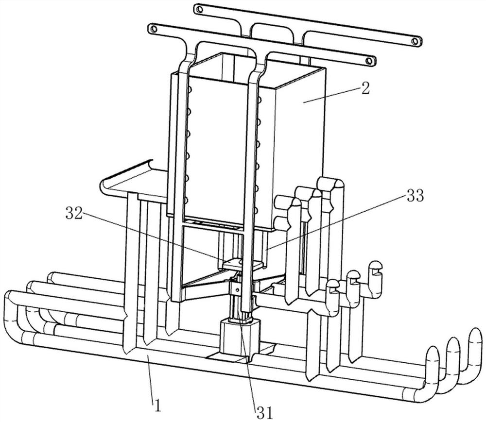
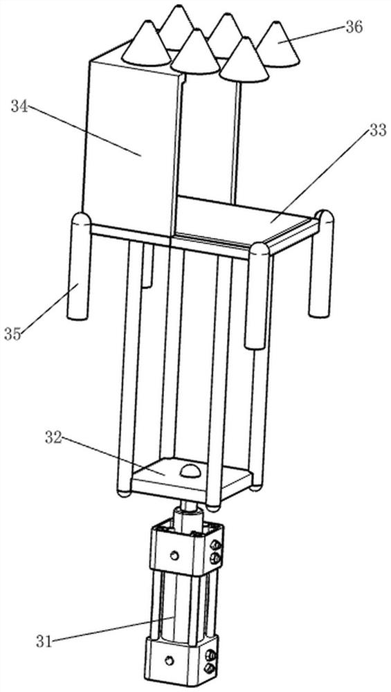
[0080] A microfiber production device based on the principle of jet spinning, such as Figure 1-Figure 5 As shown, it includes an underframe 1, an air box 2, an injection mechanism 3 and a material hanging mechanism 4. The upper and middle part of the underframe 1 is provided with an air box 2, an injection mechanism 3 is provided between the underframe 1 and the bellows 2, and an upper part of the bellows 2 is provided with Material hanging mechanism4.
[0081] When people want to make ultrafine fibers, they can use this ultrafine fiber production device based on the principle of jet spinning. First, the user injects the fiber raw materials into the injection mechanism 3, and then starts the material hanging mechanism 4 and the bellows 2 , the bellows 2 will generate a high-speed airflow, and the user starts the injection mechanism 3 again, so that the injection mechanism 3 sprays the fiber raw material, and the fiber material forms ultrafine fibers under the blown by the hig...
Embodiment 2
[0087] On the basis of Example 1, such as Figure 6-Figure 12 Shown, also include feeding mechanism 5, bellows 2 left sides are provided with feeding mechanism 5, feeding mechanism 5 includes connecting frame 51, liquid containing barrel 52, rotating plate 53, conveying pipe 54, pressing rod 55, Sliding block 56, limit rod 57 and first back-moving spring 58, bellows 2 left side front and rear two parts are all provided with connection frame 51, are connected with liquid holding bucket 52 between two connection frame 51 tops, and liquid holding bucket 52 tops rotate There is a rotating plate 53 in the formula, a delivery pipe 54 is connected between the liquid storage barrel 52 and the bellows 2, the delivery pipe 54 is connected with the material storage frame 34, and the front and rear parts on the left side of the bellows 2 are slidingly provided with a limit rod 57. A sliding block 56 is connected between the tops of the root limiting rods 57, and the sliding block 56 coope...
PUM
 Abstract
Description
Claims
Application Information
 - R&D
- Intellectual Property
- Life Sciences
- Materials
- Tech Scout
- Unparalleled Data Quality
- Higher Quality Content
- 60% Fewer Hallucinations
Browse by: Latest US Patents, China's latest patents, Technical Efficacy Thesaurus, Application Domain, Technology Topic, Popular Technical Reports.
© 2025 PatSnap. All rights reserved.Legal|Privacy policy|Modern Slavery Act Transparency Statement|Sitemap|About US| Contact US: help@patsnap.com


