
Optical element full-aperture coating device and method

A technology of optical components and coating devices, applied in optical components, optics, sputtering coating, etc., can solve the problems of high clamping stress of clamps, extrusion deformation of optical components, damage of optical components, etc., to meet the clamping requirements, The effect of preventing lateral deformation and suppressing clamping deformation

Active Publication Date: 2021-06-29
LASER FUSION RES CENT CHINA ACAD OF ENG PHYSICS
View PDF13 Cites 0 Cited by
  • Summary
  • Abstract
  • Description
  • Claims
  • Application Information

AI Technical Summary

Problems solved by technology

[0004] (1) Most of the traditional fixtures are made of metal, and the clamping stress is relatively large. The fixture directly clamps the optical element and is easy to cause damage;
[0005] (2) For optical components that require high-temperature heating, the stress caused by the deformation of the clamping device with temperature changes may easily cause extrusion deformation or even bursting of the optical components, or the gap between the clamp and the optical components may be caused by thermal expansion and contraction. Excessively large, resulting in the phenomenon of optical components falling off;
[0006] (3) The limit effect is poor, and it is easy to loosen, resulting in the substandard coating effect of a single optical component or poor consistency of the coating effect of batch components
[0007] In summary, there is an urgent need to improve the existing full-aperture coating device for optical components to avoid damage to the optical components due to excessive clamping stress, and at the same time avoid extrusion deformation or even bursting of the optical components due to clamp deformation or due to The problem that the component falls off due to excessive clearance

Method used


Image

  • Optical element full-aperture coating device and method
  • Optical element full-aperture coating device and method
  • Optical element full-aperture coating device and method

Examples


Embodiment Construction

[0044] Embodiments of the present invention are described in detail below, examples of which are shown in the drawings, wherein the same or similar reference numerals designate the same or similar elements or elements having the same or similar functions throughout. The embodiments described below by referring to the figures are exemplary and are intended to explain the present invention and should not be construed as limiting the present invention.

[0045] In the description of the present invention, it should be noted that when an element is referred to as being “fixed” or “disposed on” another element, it may be directly on the other element or indirectly on the other element. When an element is referred to as being "connected to" another element, it can be directly connected to the other element or indirectly connected to the other element.

[0046] It is to be understood that the terms "length", "width", "top", "bottom", "front", "rear", "left", "right", "vertical", "hor...


PUM


Abstract

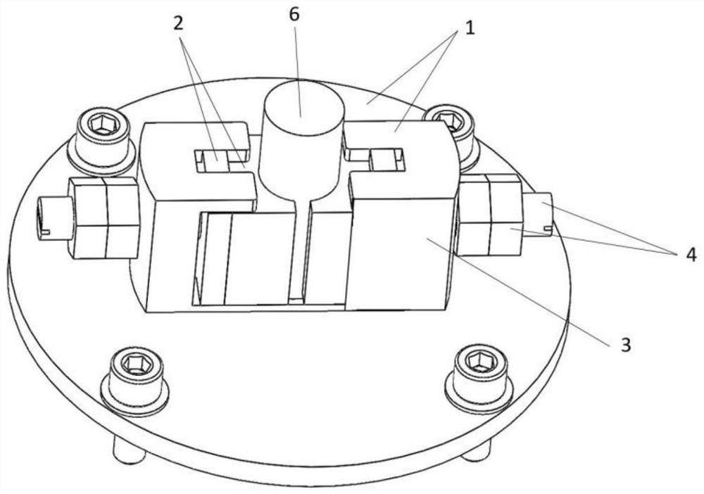
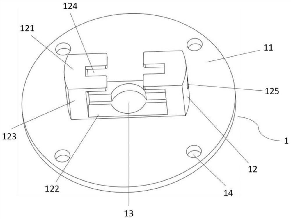
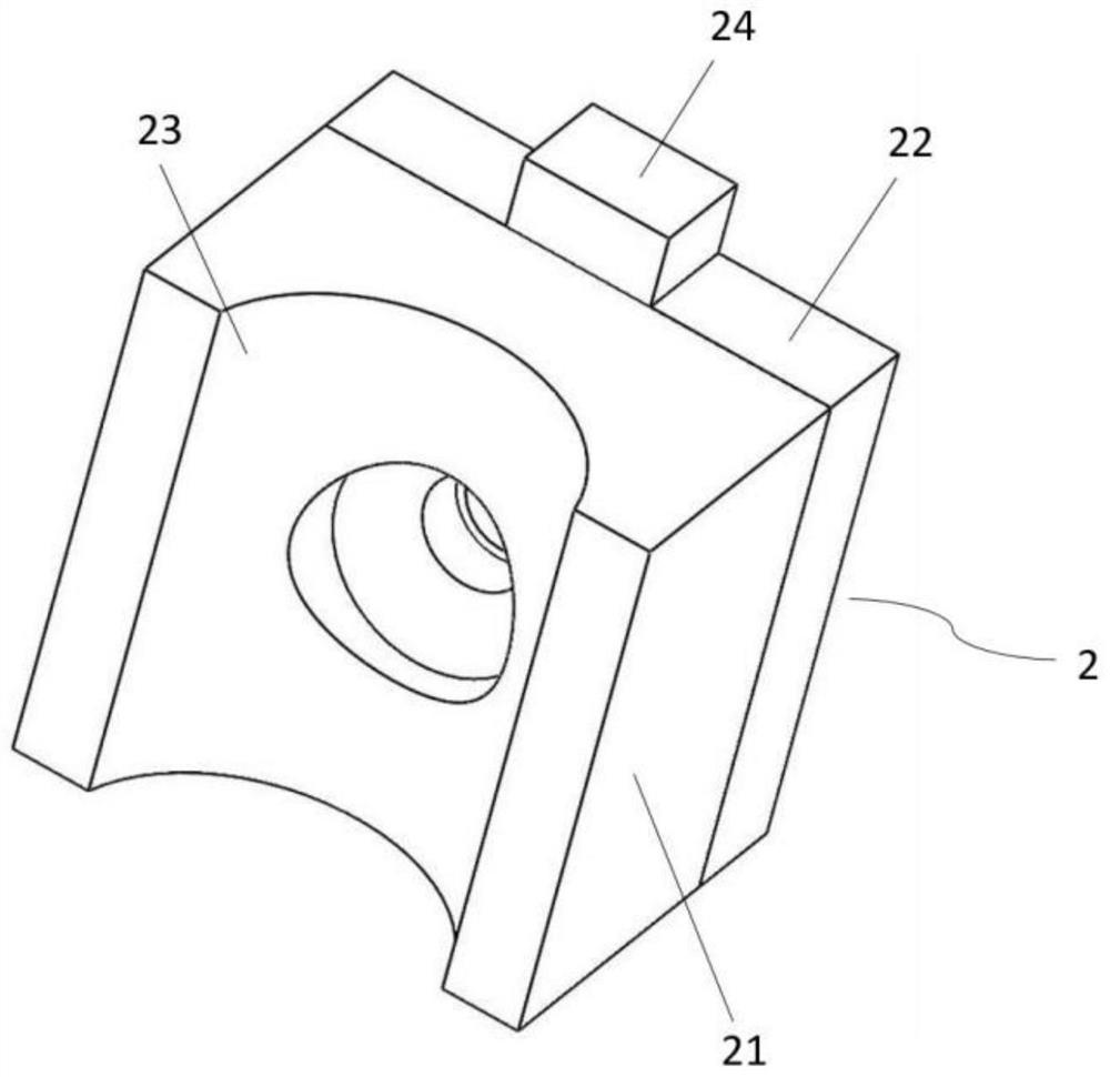
The invention is suitable for the technical field of optical element coating, and provides an optical element full-aperture coating device and method. The coating device comprises a clamping tool body, clamping assemblies, side panels and at least one jacking assembly. The clamping tool body comprises a base plate and at least two limiting blocks, a containing hole is formed in the base plate, and the limiting blocks are symmetrically arranged on the periphery of the containing hole. The clamping assemblies are arranged in the limiting blocks in a sliding mode. The side panels are arranged on the two sides of the limiting blocks and fixedly connected with the limiting blocks. Ejecting assemblies penetrate through the limiting blocks and abut against the end faces of the clamping assemblies. According to the coating device, the side panels are arranged, and the clamping assemblies are made of polytetrafluoroethylene materials, so that the coating device is high in structural strength, small in clamping stress, free of damage to optical elements, convenient and fast to use, not prone to loosening and falling off and suitable for small and medium-sized optical elements needing full-aperture coating.

Description

technical field [0001] The invention belongs to the technical field of optical element coating, and in particular relates to an optical element full-aperture coating device and a method thereof. Background technique [0002] Coating is to make optical components achieve certain optical effects, such as increasing light transmittance, anti-ultraviolet and reducing glare, ghosting, delaying lens aging and discoloration time, etc., so that a very thin film is coated on the surface of optical components. In order to ensure the quality of the coating, when the optical components are coated, it is necessary to use special fixtures to clamp and position according to the process requirements, so as to ensure that the optical components will not shift or fall when they are coated in the coating machine. On the other hand, the coating effect of optical components is stable and controlled. [0003] In the field of optical element coating, in order to meet the application requirements ...

Claims


Application Information

Patent Timeline
Patent Type & Authority Applications(China)
IPC IPC(8): C23C14/50G02B1/10
CPCC23C14/50G02B1/10
Inventor 王震卫耀伟许乔张飞吴倩罗晋李树刚罗振飞唐明刘民才
Owner LASER FUSION RES CENT CHINA ACAD OF ENG PHYSICS
Learn More