Manufacturing process of oil-immersed transformer

An oil-immersed transformer and manufacturing process technology, applied in the manufacture of inductors/transformers/magnets, electrical components, circuits, etc., can solve the problems of transformer dislocation, high labor intensity, transformer falling, etc., to improve stability and assembly. Quality and efficiency, the effect of improving quality and efficiency

Active Publication Date: 2021-06-25
中电变压器股份有限公司
View PDF28 Cites 2 Cited by
  • Summary
  • Abstract
  • Description
  • Claims
  • Application Information

AI Technical Summary

Problems solved by technology

[0003] However, the following problems exist in the assembly of existing transformers and oil tanks. a. When assembling traditional transformers and oil tanks, it is necessary to manually use tools to lift the transformer and slowly transport it into the oil tank. Due to the heavy weight of the transformer, the labor intensity of manual assembly is relatively high. Large, and manual lifting of the transformer is prone to fall, which will damage the transformer and affect the subsequent use of the oil-immersed transformer; b, when the existing oil-immersed transformer is assembled, the transformer cannot be stably clamped and transported The operation reduces the assembly efficiency of the oil-immersed transformer, and due to the sliding of the oil tank, the assembly of the transformer is dislocated, which reduces the assembly quality and efficiency of the oil-immersed transformer

Method used


Image

  • Manufacturing process of oil-immersed transformer
  • Manufacturing process of oil-immersed transformer
  • Manufacturing process of oil-immersed transformer

Examples


Embodiment Construction

[0032] The embodiments of the present invention will be described in detail below with reference to the accompanying drawings, but the present invention can be implemented in many different ways defined and covered by the claims.

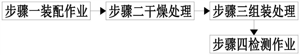
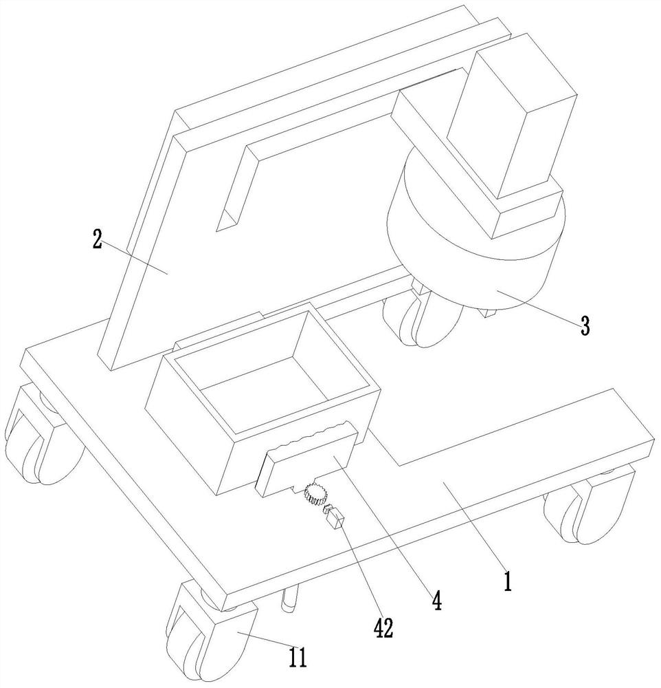
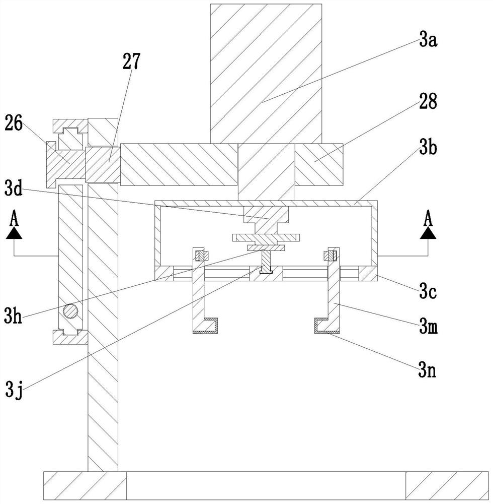
[0033] like Figure 1 to Figure 8 As shown, an oil-immersed transformer manufacturing process mainly includes the following steps:

[0034] Step 1, assembly operation, manually assembling the components of the transformer to obtain the assembled transformer;

[0035] Step 2, drying treatment, drying the assembled transformer obtained in step 1 to obtain a dried transformer;

[0036] Step 3, assembly process, install the dried transformer obtained in step 2 into the oil tank through the transformer assembly equipment, and fasten the oil tank and the transformer to obtain the assembled oil-immersed transformer;

[0037] Step 4, inspection operation, the inspection operation is performed on the assembled oil-immersed transformer obtained in step 3, a...


PUM


Abstract

The invention relates to a manufacturing process of an oil-immersed transformer. The manufacturing process mainly comprises the following steps: assembling operation, drying treatment, assembling treatment, detection operation and the like. Used transformer assembling equipment comprises a bottom plate, a conveying device, a clamping device and a positioning device. The manufacturing process of the invention can solve the following problems existing when a traditional transformer and an oil tank are assembled: a, when the traditional transformer and the oil tank are assembled, the transformer needs to be manually lifted by using a tool and slowly conveyed into the oil tank, and due to the fact that the transformer is heavy, the labor intensity of manual assembling is large, and the phenomenon that the transformer is prone to falling off when being manually lifted and causes damage to the transformer and influence on subsequent use of the oil-immersed transformer occurs; and b, when an existing oil-immersed transformer is assembled, stable clamping and conveying operation cannot be carried out on the transformer, and due to the fact that the oil tank slides, assembly of the transformer is misplaced and the assembly quality and efficiency of the oil-immersed transformer are reduced.

Description

technical field [0001] The invention relates to the technical field of transformer production, in particular to an oil-immersed transformer manufacturing process. Background technique [0002] Transformer is one of the key equipment in the power system, and it is also the most expensive and complex equipment, which undertakes power services such as voltage conversion, power distribution and transmission. Oil-immersed transformers are fully oil-filled and sealed. The corrugated oil tank shell adapts to the expansion of oil with its own elasticity and is a permanently sealed oil tank. Oil-immersed transformers have been widely used in various power distribution equipment. When producing oil-immersed transformers, the assembled transformers need to be assembled into inside the fuel tank. [0003] However, the following problems exist in the assembly of existing transformers and oil tanks. a. When assembling traditional transformers and oil tanks, it is necessary to manually u...

Claims


Application Information

Patent Timeline
IPC IPC(8): H01F41/00
CPCH01F41/00
Inventor 陈嘉静王小友
Owner 中电变压器股份有限公司
Why Eureka
Try Eureka