A Micro Electrochemical Reactor Based on Microfluidic Technology

A microfluidic technology and electrochemical technology, applied in the field of electrochemical reaction, can solve the problems of decreasing effective concentration and increasing pH on the surface of cathode catalyst, achieving the effects of low ohmic loss, large electrochemical active area, and reduced internal resistance

Active Publication Date: 2021-12-03
NANJING UNIV OF SCI & TECH
View PDF7 Cites 0 Cited by
  • Summary
  • Abstract
  • Description
  • Claims
  • Application Information

AI Technical Summary

Problems solved by technology

For hydrogen production from total water splitting, it is necessary to desorb the generated hydrogen bubbles in time to avoid occupying active sites and forming a catalytic dead zone; for the reduction of carbon dioxide, the stable existence of the three-phase interface has a great influence on the selectivity of carbon dioxide reduction products. The adsorption of carbon dioxide or water molecules on the active site determines the types of different reduction products. However, the low solubility of carbon dioxide in neutral water (0.034mol / L) and the carbonic acid, bicarbonate, carbonate, etc. The characteristics of dynamic equilibrium of chemically reduced species greatly limit the selectivity of carbon dioxide reduction products, and because the cathode reduction reaction inevitably has side reactions that consume protons to generate hydrogen, the pH of the cathode catalyst surface increases, which further leads to CO 2 drop in effective concentration

Method used


Image

  • A Micro Electrochemical Reactor Based on Microfluidic Technology
  • A Micro Electrochemical Reactor Based on Microfluidic Technology
  • A Micro Electrochemical Reactor Based on Microfluidic Technology

Examples


Embodiment 1

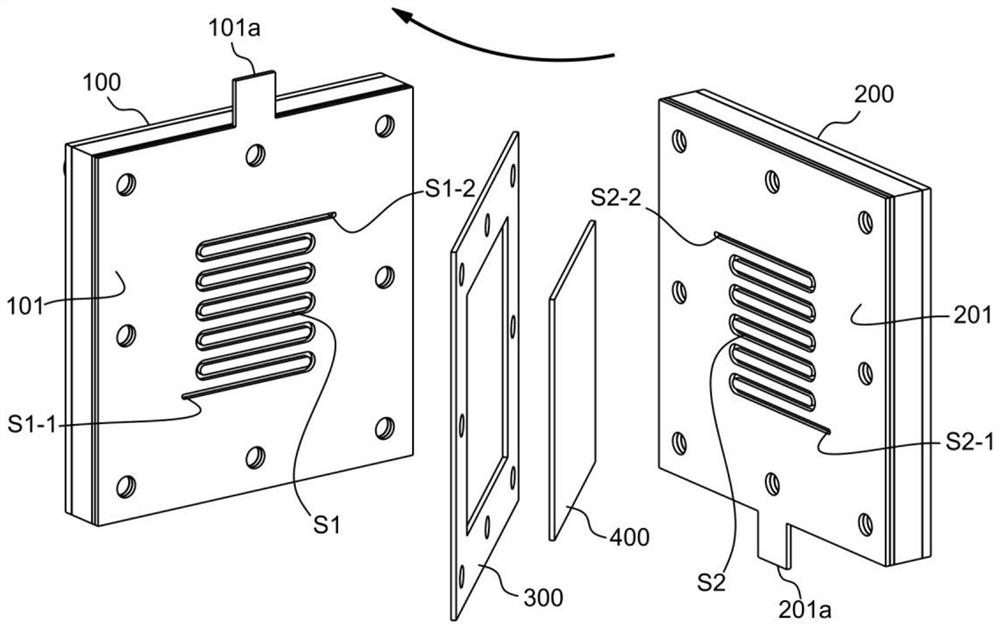
[0054] refer to figure 1 , which is the first embodiment of the present invention, this embodiment provides a micro-electrochemical reactor based on microfluidic technology, including a cathode assembly 100 and an anode assembly 200, and the anode assembly 200 and the cathode assembly 100 face each other; The assembly 100 is isolated from the anode assembly 200 by an insulator 300;

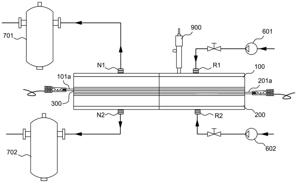
[0055] Wherein, a flow channel S1 is formed in the cathode assembly 100, a flow channel S2 is formed in the anode assembly 200, and the flow channel S1 communicates with the introduction flow channel R1 and the discharge flow channel N1 respectively, and the fluid is introduced from the introduction flow channel R1 to the flow channel S1 Among them, the fluid in the flow channel S1 is discharged from the discharge channel N1; the flow channel S2 communicates with the introduction flow channel R2 and the discharge flow channel N2 respectively, and the fluid is introduced into the flow channel S2 fr...

Embodiment 2

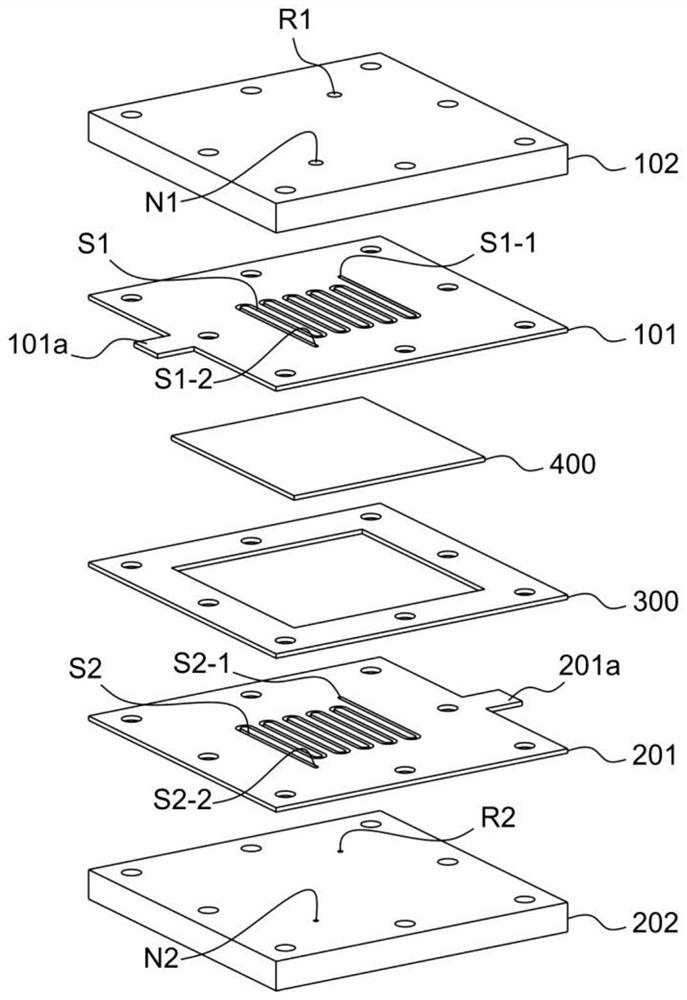
[0059] refer to Figure 2 to Figure 3 , this embodiment is different from the first embodiment in that the flow channel S1 extends from the introduction flow channel R1 to the discharge flow channel N1 to form a one-way channel, and the two ends of the one-way channel are the introduction end S1-1 and the outlet end respectively. End S1-2, the introduction end S1-1 of the flow channel S1 is connected with the introduction flow channel R1, and the outlet end S1-2 of the flow channel S1 is connected with the discharge flow channel N1;

[0060] The flow channel S2 extends from the introduction flow channel R2 to the discharge flow channel N2 to form a one-way channel. The two ends of the one-way channel are the inlet end S2-1 and the outlet end S2-2 respectively. It communicates with the introduction channel R2, and the outlet end S2-2 of the flow channel S2 communicates with the discharge channel N2; wherein, the length of the one-way channel formed by the flow channel S1 is lon...

Embodiment 3

[0063] refer to Figure 4 , this embodiment is different from the above embodiment in that: as Figure 4 As shown, the flow channel S1 and the flow channel S2 of this embodiment extend in a plane spiral shape. The working method is the same as that of the above-mentioned embodiment, and will not be repeated here.


PUM


Abstract

The invention discloses a micro-electrochemical reactor based on microfluidic technology, comprising: a cathode assembly; an anode assembly, the anode assembly and the cathode assembly face each other; and an insulating member, the cathode assembly and the cathode assembly The anode components are isolated by the insulating member; wherein, flow channels are respectively formed in the anode component and the cathode component, and the flow channels are respectively connected with the inlet flow channel and the discharge flow channel; When the cathode assemblies face each other, the flow channels overlap each other; wherein, the flow channels are separated by proton exchange membranes. Compared with the traditional H-type electrolytic cell, the internal resistance of the reactor of the present invention is greatly reduced, and the lower ohmic loss provides a better choice for realizing the application of industrial-grade current-type electrochemical catalysis.

Description

technical field [0001] The invention belongs to the technical field of electrochemical reaction, and in particular relates to a micro-electrochemical reactor based on microfluidic technology. Background technique [0002] High energy conversion efficiency, high energy conversion rate, and high Faradaic efficiency selectivity to target products have always been the industry goals in the field of electrochemical catalysis to guide the advancement and development of the scientific field. In order to achieve these three important indicators, the electrochemical reactor plays a very important role in it. Under the premise of selecting a better catalyst to achieve high Faradaic efficiency selectivity to the target product, high energy conversion efficiency corresponds to lower internal resistance of the electrochemical system, and high energy conversion rate corresponds to higher catalytic current density. The two complement each other. At the same time, in addition to selecting...

Claims


Application Information

Patent Timeline
Patent Type & Authority Patents(China)
IPC IPC(8): C25B9/19C25B11/073C25B1/04C25B1/27C25B3/26C25B3/03
CPCC25B1/00C25B1/04Y02E60/36
Inventor 冯浩施桐刘东张莹李强
Owner NANJING UNIV OF SCI & TECH
Why Eureka
Try Eureka