Fluorescent material coating method
A fluorescent material and coating method technology, applied in the field of fluorescent materials, can solve problems such as uneven coating, achieve uniform and dense coating, avoid local deposition, and improve product qualification rate
- Summary
- Abstract
- Description
- Claims
- Application Information
AI Technical Summary
Problems solved by technology
Method used
Image
Examples
Embodiment 1
[0026] Example 1: BaMg 2 al 16 o 27 :Eu and MgAl 11 o 19 : (Ce, Tb) Fluorescent material combined at a volume ratio of 1:1; cylindrical LED lamp tube with a radius of 5cm and a length of 40cm
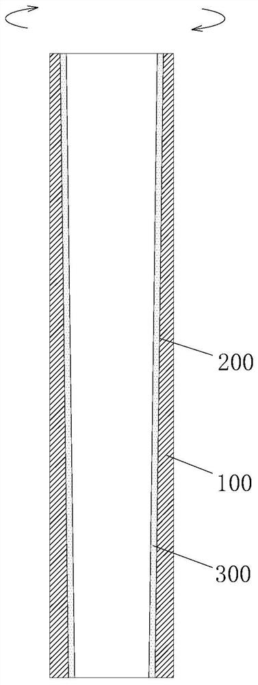
[0027] Such as figure 1 Shown, a kind of fluorescent material coating method, the step comprises:
[0028] Step 1: Process the inner surface of the LED lamp tube 100 by etching to form a gradient slope 200 with an inner diameter, and the inclination angle is 0.5° (the angle with the vertical surface, the same below);
[0029] Step 2: Dispersing the fluorescent material in ethanol to form a fluorescent material solution, the volume ratio of the fluorescent material to the solvent in the fluorescent material solution is 1:0.8;
[0030] Step 3: Place the LED tube vertically with the larger end of the LED tube facing up, inject the fluorescent material solution into the LED tube, and apply a rotating force to the LED tube to make the LED tube rotate at a constant speed. Rotate horizo...
Embodiment 2
[0032] Embodiment 2: (BaSi 2 o 3 ): Pb fluorescent material; a cylindrical LED tube with a radius of 5cm and a length of 40cm
[0033] A method for coating a fluorescent material, the steps comprising:
[0034] Step 1: Treat the inner surface of the LED lamp tube by etching to form a gradient slope with an inner diameter of 1°;
[0035] Step 2: Dispersing the fluorescent material in deionized water to form a fluorescent material solution, the volume ratio of the fluorescent material to the solvent in the fluorescent material solution is 1:1.5;
[0036] Step 3: Place the LED tube vertically with the larger end of the LED tube facing up, inject the fluorescent material solution into the LED tube, and apply a rotating force to the LED tube to make the LED tube rotate at a constant speed. Rotate horizontally at a speed of 1012r / min;
[0037] Step 4: During the horizontal rotation of the LED lamp tube, vacuum drying at a temperature of 100° C. is used to cure the fluorescent ma...
Embodiment 3
[0038] Example 3: Y(PV)O 4 : Eu fluorescent material; cylindrical LED tube with a radius of 5cm and a length of 40cm
[0039] A method for coating a fluorescent material, the steps comprising:
[0040] Step 1: Treat the inner surface of the LED lamp tube by grinding to form a gradient slope with an inner diameter of 1.5°;
[0041] Step 2: Dispersing the fluorescent material in oxalic acid to form a fluorescent material solution, the volume ratio of the fluorescent material to the solvent in the fluorescent material solution is 1:2.5;
[0042] Step 3: Place the LED tube vertically with the larger end of the LED tube facing up, inject the fluorescent material solution into the LED tube, and apply a rotating force to the LED tube to make the LED tube rotate at a constant speed. Rotate horizontally at a speed of 826r / min;
[0043] Step 4: During the horizontal rotation of the LED lamp tube, vacuum drying at a temperature of 150° C. is used to cure the fluorescent material solut...
PUM
 Abstract
Description
Claims
Application Information
 - R&D
- Intellectual Property
- Life Sciences
- Materials
- Tech Scout
- Unparalleled Data Quality
- Higher Quality Content
- 60% Fewer Hallucinations
Browse by: Latest US Patents, China's latest patents, Technical Efficacy Thesaurus, Application Domain, Technology Topic, Popular Technical Reports.
© 2025 PatSnap. All rights reserved.Legal|Privacy policy|Modern Slavery Act Transparency Statement|Sitemap|About US| Contact US: help@patsnap.com


