Method and device for modifying surfaces of inner wall and outer wall of cavity based on ultrasonic cavitation
A surface modification and ultrasonic technology, which is used in devices for coating liquids on surfaces, special surfaces, pretreated surfaces, etc. strong effect
- Summary
- Abstract
- Description
- Claims
- Application Information
AI Technical Summary
Problems solved by technology
Method used
Image
Examples
Embodiment 1
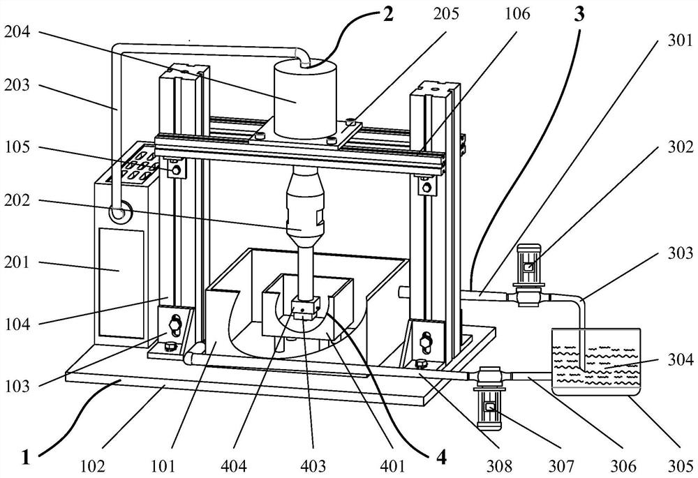
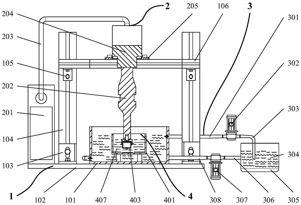
[0049] The device for modifying the inner and outer walls of a cavity based on ultrasonic cavitation includes a device support unit 1 , an ultrasonic cavitation unit 2 , a coolant circulation unit 3 and a workpiece clamping unit 4 .
[0050] The device support unit 1 includes a water tank 101, a platform bottom plate 102, a connector I 103, a support column 104, a connector II 105 and a support beam 106; the water tank 101 is used to store the cooling liquid 304; the connector I 103 will The supporting column 104 is fixed on the platform floor 102 ; the connecting piece II 105 fixes the supporting beam 106 on the supporting column 104 .
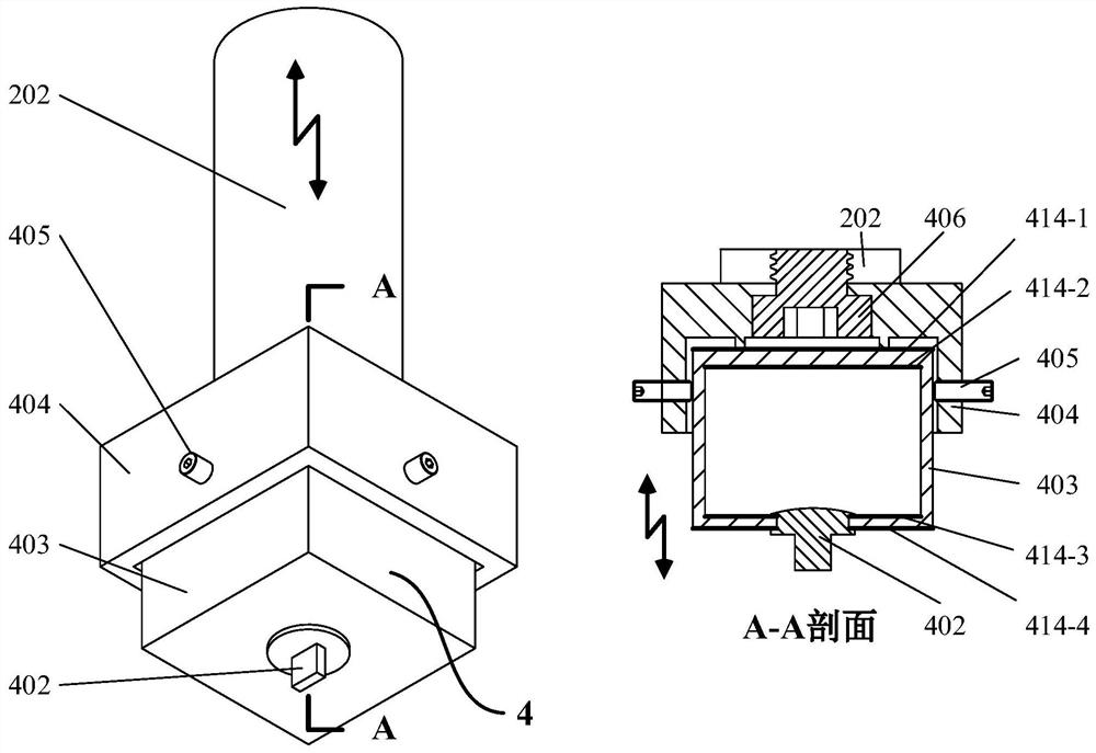
[0051] The ultrasonic cavitation unit includes a power supply 201, a horn 202, electric wires 203, an ultrasonic generator 204 and a generator support base 205; the power supply 201 is an ultrasonic excitation device, which can control frequency, amplitude and working time; The center of the bottom surface of the rod 202 is provided with a thre...
Embodiment 2
[0055] This embodiment is the steps of modifying the surface of the inner and outer walls of the copper cavity workpiece:
[0056] Step 1. Rinse the copper cavity workpiece 403 with a size of 20mm×20mm×16mm, a wall thickness of 2mm, and an inlet diameter of 6mm with tap water; add 2g of modified silica particles 411 with a particle size of 20nm to 25mL of absolute ethanol and 25mL of distilled water mixture, stirred in a 300rpm magnetic stirrer for 5min to obtain the modified solution 407, which was loaded into the modified solution container 401; the cooling liquid 304 was poured into the cooling liquid container 305, and the extrusion pump 302 was started and pressed into the Pump 307, starts coolant circulation.
[0057] Step 2, tighten the cavity workpiece 403 by fastening screws 405 image 3 The bottom surface modified installation method shown is clamped to the workpiece fixture 404; the horn 202 is inserted into the modified liquid container 401 so that the cavity work...
Embodiment 3
[0061] This embodiment is the step of modifying the surface of the outer wall surface of the brass cavity workpiece:
[0062] Step 1. Rinse the brass cavity workpiece 403 with a size of 20mm×20mm×16mm, a wall thickness of 2mm, and an inlet diameter of 6mm with tap water; add 2g of modified silica particles 411 with a particle size of 20nm to 25mL of anhydrous In the mixture of ethanol and 25mL distilled water, stir in a 300rpm magnetic stirrer for 5 minutes to obtain the modified liquid 407, which is loaded into the modified liquid container 401; the cooling liquid 304 is poured into the cooling liquid container 305, and the extrusion pump 302 and the pressure pump 302 are started. Into the pump 307, start the coolant circulation.
[0063] Step 2: Seal the cavity workpiece 403 with the sealing cover 402 .
[0064] Step 3, tighten the cavity workpiece 403 by fastening screws 405 and image 3 The installation method shown for bottom surface modification is clamped to the workp...
PUM
| Property | Measurement | Unit |
|---|---|---|
| particle diameter | aaaaa | aaaaa |
Abstract
Description
Claims
Application Information
 - R&D
- Intellectual Property
- Life Sciences
- Materials
- Tech Scout
- Unparalleled Data Quality
- Higher Quality Content
- 60% Fewer Hallucinations
Browse by: Latest US Patents, China's latest patents, Technical Efficacy Thesaurus, Application Domain, Technology Topic, Popular Technical Reports.
© 2025 PatSnap. All rights reserved.Legal|Privacy policy|Modern Slavery Act Transparency Statement|Sitemap|About US| Contact US: help@patsnap.com


