Subsurface defect detection device

A sub-surface defect and detection device technology, applied in the field of defect detection, can solve the problems of high synchronization control stability requirements, strong mechanical vibration interference, low detection efficiency and speed, etc., to avoid mechanical vibration interference and improve imaging efficiency and speed , The effect of reducing the difficulty of synchronous control

Pending Publication Date: 2021-06-22
CHIBI JINGMAI OPTOELECTRONIC TECH CO LTD
View PDF8 Cites 1 Cited by
  • Summary
  • Abstract
  • Description
  • Claims
  • Application Information

AI Technical Summary

Problems solved by technology

[0005] However, the existing detection devices often have the problems of strong mechanical vibration interference, high requirements for synchronous control stability, and low detection efficiency and speed.

Method used


Image

  • Subsurface defect detection device
  • Subsurface defect detection device
  • Subsurface defect detection device

Examples


Embodiment Construction

[0034] It can be seen from the background technology that the detection devices for subsurface defects in the prior art have the problems of strong mechanical vibration interference, high difficulty in synchronous control, and low detection efficiency and speed. The reasons for the above problems are now analyzed in combination with a detection device for subsurface defects:

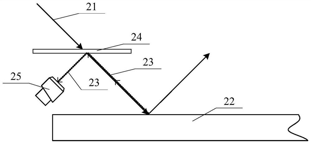
[0035] refer to figure 1 , shows a schematic diagram of the optical path of a detection device for subsurface defects.

[0036] The illumination light 21 produced by the light source (not shown in the figure) is incident on the surface of the object to be imaged 22; ray 23 for imaging.

[0037] In order to improve the local illumination light intensity, the imaging device generally adopts a line light source to generate illumination light 21, so the formed illumination light 21 is a one-dimensional light in the direction perpendicular to the paper surface; , the incident position of the illuminating l...


PUM

PropertyMeasurementUnit
thicknessaaaaaaaaaa

Abstract

A subsurface defect detection device comprises: a light source assembly suitable for generating illumination light, the illumination light being divergent light, wherein the illumination light is coupled into a to-be-detected piece to form waveguide light, and the waveguide light is propagated in the to-be-detected piece in a guided wave mode; an imaging assembly which comprises an area array image sensor, wherein the area array image sensor is suitable for collecting the scattered waveguide light to obtain a defect image; and a processing assembly which is suitable for processing the defect image. The detection device can realize multi-angle detection so as to improve the imaging efficiency; moreover, an area array image sensor is adopted in the imaging assembly to obtain defect images, and the defect images are matched with divergent illumination light, so that the introduction of a scanning mode can be avoided, mechanical vibration interference is avoided, and the synchronous control difficulty is reduced.

Description

technical field [0001] The invention relates to the field of defect detection, in particular to a detection device for subsurface defects. Background technique [0002] Large-scale high-power laser devices such as the National Ignition Device of the United States, the megajoule laser device of France, and the Shenguang series devices of China usually require the use of a certain number of large-aperture optical components. Defects of optical components not only affect its long-term stability, coating quality and surface shape accuracy, but also directly reduce the laser damage threshold of the optical system, affecting its beam quality and service life. Subsurface imaging of optical components, especially for the characterization of subsurface defects, is particularly important for the effective detection of defects in optical components. [0003] The current characterization methods of subsurface defects can be divided into two categories: destructive detection methods and...

Claims


Application Information

Patent Timeline
Patent Type & Authority Applications(China)
IPC IPC(8): G01N21/01G01N21/95
CPCG01N21/01G01N21/95
Inventor 冯胜翟中生王选择谢博娅
Owner CHIBI JINGMAI OPTOELECTRONIC TECH CO LTD
Why Eureka
Try Eureka