Gas brake system for loader

A gas brake, loader technology, applied in the direction of brakes, brake components, brake transmission devices, etc., can solve the problem of icing of brake pipes

Active Publication Date: 2022-01-28
QINGDAO LOVOL EXCAVATOR
View PDF0 Cites 0 Cited by
  • Summary
  • Abstract
  • Description
  • Claims
  • Application Information

AI Technical Summary

Problems solved by technology

[0005] The purpose of the present invention is to solve the technical problem that the brake pipeline is easy to freeze when the vehicle brake system is in the high cold and high altitude area

Method used


Image

  • Gas brake system for loader
  • Gas brake system for loader
  • Gas brake system for loader

Examples


Embodiment Construction

[0038] The specific implementation manners of the present invention will be further described in detail below in conjunction with the accompanying drawings and embodiments. The following examples are used to illustrate the present invention, but are not intended to limit the scope of the present invention.

[0039] The following is a description of preferred embodiments of the present invention in conjunction with the accompanying drawings.

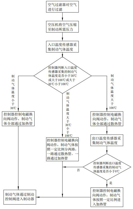
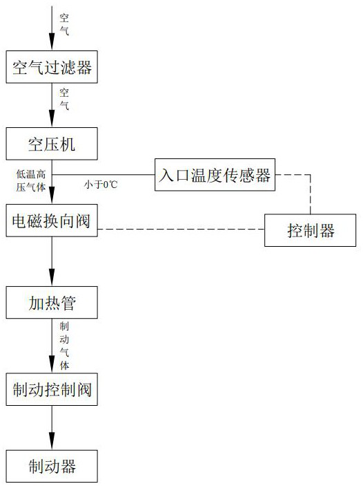
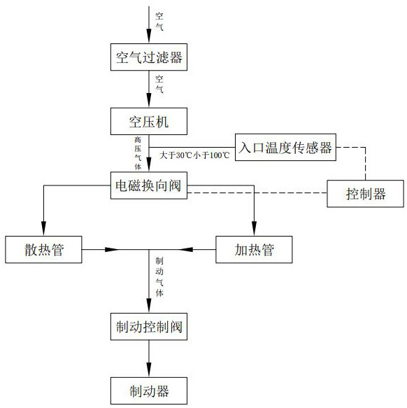
[0040] A gas braking system for a loader, comprising:

[0041] Air delivery unit: including an air compressor for compressing air;

[0042] Air distribution unit: the air distribution unit is connected to the air compressor through pipelines;

[0043] Temperature data acquisition unit: including the inlet temperature sensor, which is installed in the connecting pipe between the gas transmission unit and the gas distribution unit;

[0044] Controller: it is respectively connected to the temperature data acquisition unit and the gas dist...


PUM


Abstract

The invention discloses a gas braking system for a loader, which includes: a gas transmission unit; a gas distribution unit: the gas distribution unit is connected to an air compressor through a pipeline; a temperature data acquisition unit: including an inlet temperature sensor; a controller: its Communication connection with temperature data acquisition unit and gas distribution unit respectively; gas temperature control unit: including heating tube. The method for controlling the gas temperature by using the system includes the following steps: Step 1: The air compressor compresses the air to the pressure required for braking; Step 2: The inlet temperature sensor collects the temperature of the brake gas; Step 3: The controller judges this Whether the temperature is less than 30°C; Step 4: If the brake gas temperature data is less than 30°C, the controller controls the air distribution unit to make the brake gas enter the heating tube; Step 5: The heating tube heats the brake gas, using this scheme It can make the vehicle work in the cold and high-altitude area, use the heating tube to heat the brake gas, and avoid the water in the brake pipeline from being too cold and freezing.

Description

technical field [0001] The invention relates to a gas braking system for a loader. Background technique [0002] The engineering vehicle brake basically adopts air brake. The working process is to use the air compressor (hereinafter referred to as the air compressor) to compress the air into high-pressure gas, and push the brake through the high-pressure gas to brake the whole vehicle. For details, refer to the attached Figure 5 After the air is compressed into high-temperature and high-pressure air by an air compressor, the heat dissipation pipe (usually copper or aluminum pipe) is used for sufficient heat dissipation, and then converted into normal temperature and high-pressure brake gas to push the brake for vehicle braking. [0003] In the prior art, when the vehicle brakes, the air is first compressed into high-temperature and high-pressure brake gas through the air compressor, and then converted into normal temperature and high-pressure gas through the heat dissipation...

Claims


Application Information

Patent Timeline
Patent Type & Authority Patents(China)
IPC IPC(8): B60T17/00B60T13/26
CPCB60T17/002B60T13/26
Inventor 赵斌王洪云胡月平蒙小行宋赛刘虹
Owner QINGDAO LOVOL EXCAVATOR
Why Eureka
Try Eureka