Eureka AIR delivers breakthrough ideas for toughest innovation challenges, trusted by R&D personnel around the world.

Motor rotor shaft forming machining process

A technology for motor rotor shaft and forming processing, applied in metal processing equipment, manufacturing tools, grinding workpiece supports, etc., can solve the problems of inability to guarantee, poor grinding effect, low grinding efficiency, etc., and achieve efficient and fast grinding process. High efficiency and low grinding cost

Inactive Publication Date: 2021-06-22
梅世春
View PDF0 Cites 2 Cited by
  • Summary
  • Abstract
  • Description
  • Claims
  • Application Information

AI Technical Summary

Problems solved by technology

[0005] The present invention can solve the following difficult problems that may be encountered in the grinding process of the existing cone-shaped motor rotor shaft: a. The outer wall of the cone-shaped motor rotor shaft is manually polished with sandpaper, and the required labor force is relatively large. And the grinding takes a long time, resulting in low grinding efficiency; b. With manual grinding, the grinding effect can only be judged according to the experience of the grinding workers, which cannot be guaranteed, and uneven grinding may occur, resulting in higher grinding costs and poor grinding effects. poor

Method used


Image

  • Motor rotor shaft forming machining process
  • Motor rotor shaft forming machining process
  • Motor rotor shaft forming machining process

Examples


Embodiment Construction

[0039] Embodiments of the present invention will be described below with reference to the drawings. In the process, in order to ensure the clarity and convenience of illustration, we may exaggerate the width of the lines or the size of the constituent elements in the diagram.

[0040] In addition, the following terms are defined based on the functions in the present invention, and may be different according to the user's or operator's intention or practice. Therefore, these terms are defined based on the entire content of this specification.

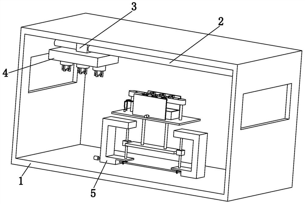
[0041] Such as Figure 1 to Figure 11 As shown, a motor rotor shaft molding process, which uses a motor rotor shaft molding processing equipment, the motor rotor shaft molding processing equipment includes a frame 1, a sliding shaft 2, an electric slider 3, a clamping device 4 and Grinding device 5, when using the above-mentioned motor rotor shaft forming processing equipment to process the conical motor rotor shaft, the specific metho...


PUM


Abstract

The invention relates to a motor rotor shaft forming machining process. A motor rotor shaft forming machining device comprises a frame body, a sliding shaft, an electric sliding block, a clamping device and a grinding device, wherein the sliding shaft is installed at the upper end of the interior of the frame body, the electric sliding block is slidably installed at the position, close to the left end, of the sliding shaft, the clamping device is fixedly connected to the lower end face of the electric sliding block, and the grinding device is arranged at the lower end in the frame body. The grinding device can solve the following problems possibly occurring in the grinding process of an existing conical motor rotor shaft: a, the outer side wall of the conical motor rotor shaft is manually subjected to circumferential grinding treatment by using abrasive paper, the required labor force is large, the grinding time is long, and the grinding efficiency is low; and b, manual grinding is adopted, the grinding effect can only be judged according to the experience of grinding workers and cannot be guaranteed, the situation of uneven grinding possibly occurs, the grinding cost is high, and the grinding effect is poor.

Description

technical field [0001] The invention relates to the field of motor rotor shaft forming processing, in particular to a motor rotor shaft forming process. Background technique [0002] The rotor shaft of the motor is the shaft used to install the rotor in the motor, which plays a role in transmitting the power of the motor. In order to improve the use safety and braking effect of the motor, it is usually necessary to process the rotor shaft of the motor into a tapered shape. When manufacturing the rotor shaft of the conical motor, it is necessary to cut the fixed-length circular segment into a cone shape first, and then go through hobbing, burr treatment, coating treatment and performance test before it can be put into use. During the process of cutting and storing the tapered circular segment after cutting, a small amount of burrs and dirt are often attached to the surface. If it is not cleaned in time, the appearance and quality of the rotor shaft of the tapered motor may b...

Claims


Application Information

Patent Timeline
Patent Type & Authority Applications(China)
IPC IPC(8): B24B1/00B24B21/02B24B21/18B24B41/06B24B41/00
CPCB24B1/00B24B21/02B24B21/18B24B41/00B24B41/005B24B41/06
Inventor 梅世春
Owner 梅世春
Why Eureka
Eureka Blog
Learn More