Multi-chamber magnetic control multilayer optical coating equipment and method

An optical coating and magnetron technology, applied in coating, sputtering coating, ion implantation coating, etc., can solve the problems that the uniformity of the working gas is difficult to control, affects the coating quality of the workpiece, and the quality of the coating layer of the workpiece is different. , to achieve the effect of improving vacuum uniformity, high consistency, and improving coating quality

Active Publication Date: 2021-06-18
ZHAOQING KERUN VACUUM EQUIP
View PDF4 Cites 2 Cited by
  • Summary
  • Abstract
  • Description
  • Claims
  • Application Information

AI Technical Summary

Problems solved by technology

[0003] In actual production, since the vacuum coating equipment with a single furnace structure has only one vacuum chamber, the furnace body needs to be filled with atmosphere after each coating, and the opening time of each vacuum chamber door is different, so it is easy to It will affect the atmosphere changes in the vacuum chamber, and the vacuum degree will fluctuate greatly. In the end, the properties of the film layer of the workpiece after each furnace will be different, and the quality of the film layer of the workpiece will be different.
[0004] In the linear vacuum coating equipment with multiple chambers connected in series, each coating chamber usually adopts a rectangular structure, and the magnetron targets in the coating chamber can only be distributed on the two side walls of the coating chamber, which makes it difficult to achieve a uniform arrangement. Each coating chamber, therefore, the channels between adjacent coating chambers are generally relatively large. During the coating operation, the coating chamber needs to be inflated with working gas, and the arrangement of the gas baffle is quite difficult. The uniformity of the gas on the magnetron target is also difficult to control, and eventually it is easy to affect the coating quality of the workpiece

Method used


Image

  • Multi-chamber magnetic control multilayer optical coating equipment and method
  • Multi-chamber magnetic control multilayer optical coating equipment and method
  • Multi-chamber magnetic control multilayer optical coating equipment and method

Examples


Embodiment 1

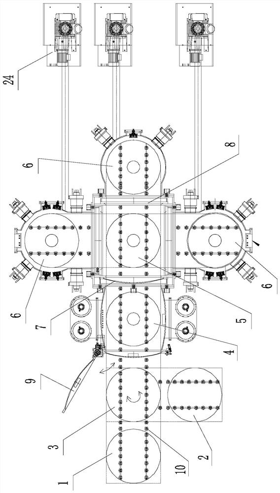
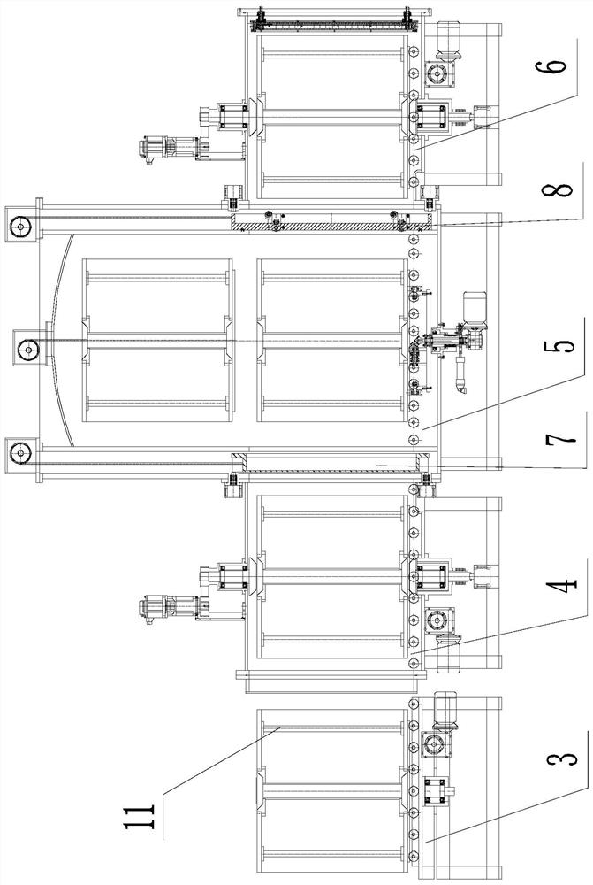
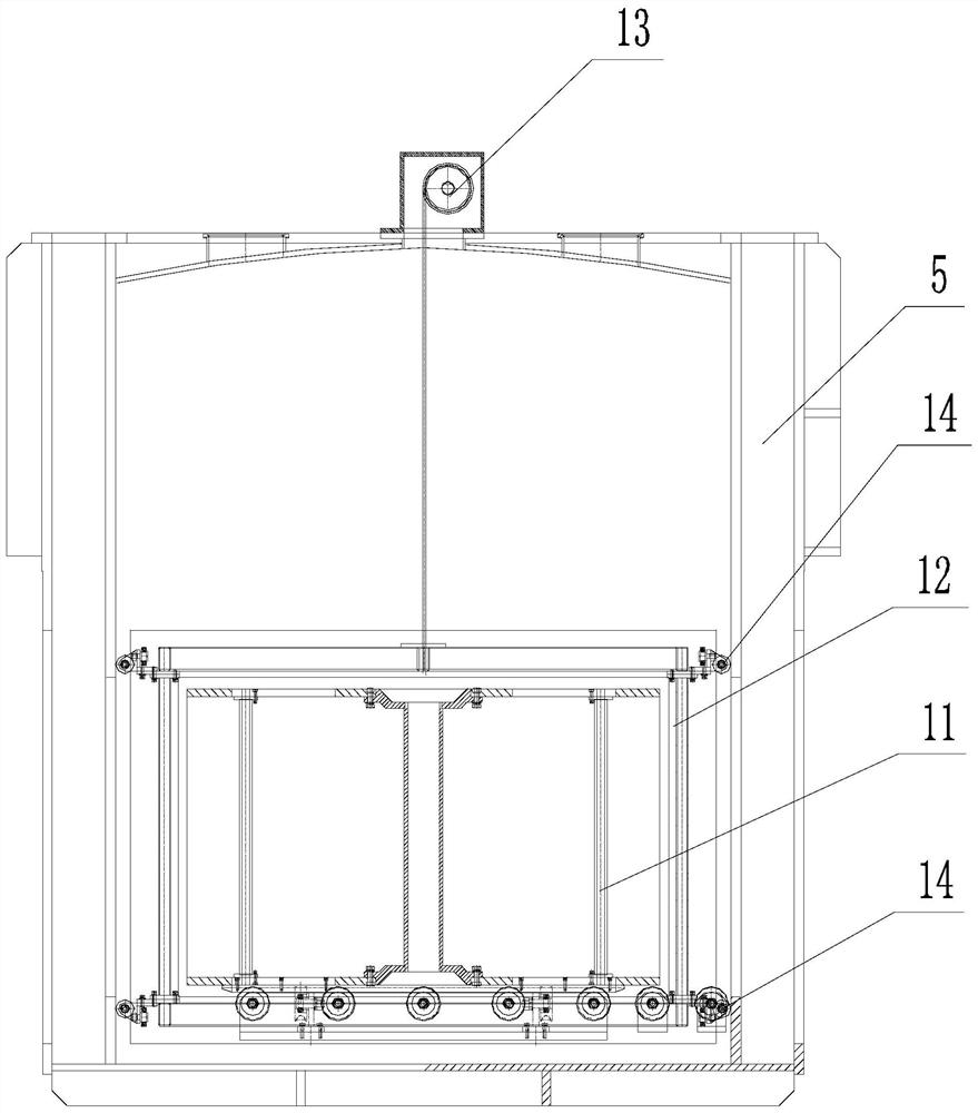
[0046] This embodiment is a multi-chamber magnetron multi-layer optical coating equipment, such as figure 1 As shown, it includes a workpiece loading platform 1, a workpiece unloading platform 2, a workpiece in and out device 3, a pretreatment chamber 4, a workpiece in and out conversion chamber 5, and three coating chambers 6. The pretreatment chamber and the three coating chambers are distributed in the workpiece in and out. Around the conversion chamber, the workpiece loading platform and the workpiece unloading platform are distributed on the two outer sides of the workpiece in and out of the device in different directions. A first vacuum door valve mechanism 7 is provided at the connection between the workpiece in and out of the conversion chamber and the pretreatment chamber, and a second vacuum door valve mechanism 8 is provided at the connection between the workpiece in and out of the conversion chamber and each coating chamber, and the pretreatment chamber faces the wo...

Embodiment 2

[0057] The present embodiment is a multi-chamber magnetron multilayer optical coating method, which is realized by the coating equipment described in Embodiment 1, and includes the following steps:

[0058] (1) The workpiece rack carries each workpiece, and is sent into the pretreatment chamber by the workpiece entry and exit device for ion surface treatment;

[0059] (2) after finishing the ion surface treatment, open the first vacuum gate valve mechanism, wait for the workpiece rack of the workpiece coating to enter the workpiece entry and exit conversion chamber, and then close the first vacuum gate valve mechanism;

[0060] (3) The workpiece rack waiting for the workpiece to be coated is lifted to the upper part of the workpiece in and out of the conversion chamber;

[0061] (4) After the coating of one of the coating chambers is completed, first open the second vacuum gate valve mechanism and send out the workpiece rack that has completed the workpiece coating, then close...


PUM


Abstract

The invention discloses multi-chamber magnetic control multilayer optical coating equipment and method. The equipment comprises a workpiece in-out device, a pretreatment chamber, a workpiece in-out conversion chamber and a plurality of coating chambers which are connected in sequence, wherein the pretreatment chamber and the plurality of coating chambers are distributed at the periphery of the workpiece in-out conversion chamber; and a first vacuum gate valve mechanism is arranged between the workpiece in-out conversion chamber and the pretreatment chamber, a second vacuum gate valve mechanism is arranged between the workpiece in-out conversion chamber and each coating chamber, and a revolving door mechanism is arranged at the side, facing the workpiece in-out device, of the pretreatment chamber. The method comprises the following steps of conducting ion surface treatment on a workpiece on a work rest by the pretreatment chamber, then entering the workpiece in-out conversion chamber and lifting to the upper part, after one of the coating chambers finishes coating, sending out the work rest and the workpiece through the workpiece in-out conversion chamber, and descending a work rest to be coated and sending the work rest to be coated into the coating chamber. According to the equipment and the method, the vacuum degree uniformity between the coating chambers can be effectively improved, so that the consistency of the film layer performance of the coated workpiece is improved, and the coating quality of the workpiece is improved.

Description

technical field [0001] The invention relates to the technical field of vacuum coating, in particular to a multi-chamber magnetron multilayer optical coating device and a coating method. Background technique [0002] In the field of vacuum coating technology, traditional vacuum coating equipment mostly adopts the structure of a single furnace body or a linear multi-chamber series structure. [0003] In actual production, the vacuum coating equipment in the form of a single furnace structure has only one vacuum chamber, and the furnace body needs to be filled with atmosphere after each coating is completed, and the time for opening the door of the vacuum chamber is different each time, so it is easy to It affects the change of atmosphere in the vacuum chamber, and the degree of vacuum fluctuates greatly. In the end, the performance of the workpiece film after each furnace processing will be different, and the quality of the workpiece film will be different. [0004] In the li...

Claims


Application Information

Patent Timeline
Patent Type & Authority Applications(China)
IPC IPC(8): C23C14/35C23C14/56
CPCC23C14/35C23C14/56C23C14/564C23C14/568
Inventor 朱建明
Owner ZHAOQING KERUN VACUUM EQUIP
Why Eureka
Try Eureka