
Surface treatment device of stainless steel pipe for building construction and working method of surface treatment device

A technology of surface treatment device and stainless steel tube, which is applied in the direction of grinding drive device, manufacturing tool, grinding workpiece support, etc., can solve the problems of secondary clamping work efficiency of stainless steel tube, etc. Effect

Inactive Publication Date: 2021-06-18
潘文超
View PDF0 Cites 4 Cited by
  • Summary
  • Abstract
  • Description
  • Claims
  • Application Information

AI Technical Summary

Problems solved by technology

[0005] In order to solve the deficiencies mentioned in the above-mentioned background technology, the object of the present invention is to provide a surface treatment device and working method of stainless steel pipes for building construction, which solves the need for secondary clamping and low work efficiency when polishing stainless steel pipes The problem

Method used


Image

  • Surface treatment device of stainless steel pipe for building construction and working method of surface treatment device
  • Surface treatment device of stainless steel pipe for building construction and working method of surface treatment device
  • Surface treatment device of stainless steel pipe for building construction and working method of surface treatment device

Examples


Embodiment Construction

[0040] The following will clearly and completely describe the technical solutions in the embodiments of the present invention with reference to the accompanying drawings in the embodiments of the present invention. Obviously, the described embodiments are only some, not all, embodiments of the present invention. Based on the embodiments of the present invention, all other embodiments obtained by persons of ordinary skill in the art without creative efforts fall within the protection scope of the present invention.

[0041] In describing the present invention, it is to be understood that the terms "opening", "upper", "lower", "thickness", "top", "middle", "length", "inner", "surrounding" etc. Indicating orientation or positional relationship is only for the convenience of describing the present invention and simplifying the description, and does not indicate or imply that the components or elements referred to must have a specific orientation, be constructed and operated in a sp...


PUM


Abstract

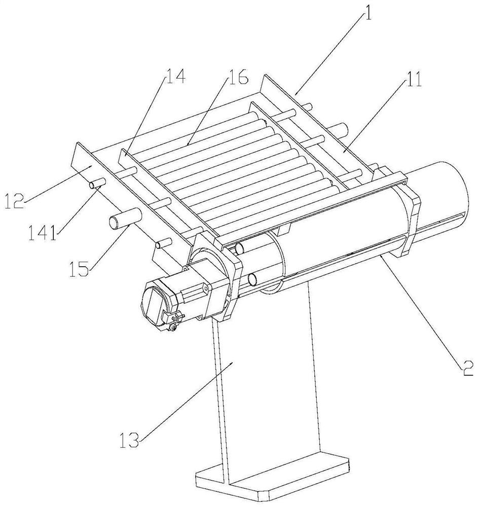
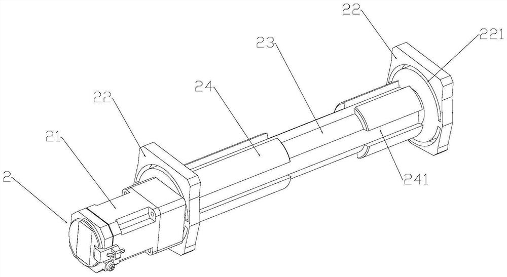
The invention relates to the field of stainless steel pipes, in particular to a surface treatment device of a stainless steel pipe for building construction and a working method thereof. The surface treatment device comprises a discharging mechanism, a side wall treatment mechanism, a supporting mechanism, an end face treatment mechanism, a blocking mechanism and a material collecting mechanism. During use, stainless steel pipes in the discharging mechanism are released to fall into a limiting groove, a first motor, a rotating roller and the three stainless steel pipes are driven to rotate, the stainless steel pipes and the frosted inner wall of an arc-shaped plate are polished and derusted, other parts do not need to be moved during polishing, and sufficient polishing can be achieved through rotation of the rotating roller. the side walls of three stainless steel pipes can be treated through one-time polishing, the working efficiency is improved, after the steel pipes fall down, a second motor drives a polishing wheel to move towards the inner side until a limiting column enters the inner walls of the stainless steel pipes, so that the side walls of the polishing wheel are attached to the ends of the stainless steel pipes, and the polishing wheel rotates to polish the ends of the stainless steel pipes. The number of stainless steel polished at a time is three, and the working efficiency is improved.

Description

technical field [0001] The invention relates to the field of stainless steel pipes, in particular to a surface treatment device for stainless steel pipes used in building construction and a working method thereof. Background technique [0002] In the construction field, after the steel pipe is formed, in order to improve the production and processing quality of the steel pipe, ensure the performance of the steel pipe, and improve the accuracy of the building, the steel pipe needs to be polished to remove the burrs and rust on the surface of the steel pipe. [0003] The existing steel pipe grinding method is usually to fix both ends of the steel pipe. After the position of the steel pipe is fixed, the side wall of the steel pipe is polished by the rotation of the grinding wheel. Through the rotation of the grinding wheel, the outer circumference of the grinding wheel rubs against the surface of the steel pipe. And the steel pipe is polished, but, because the steel pipe is a c...

Claims


Application Information

Patent Timeline
Patent Type & Authority Applications(China)
IPC IPC(8): B24B1/00B24B27/00B24B41/00B24B41/02B24B41/06B24B47/12B24B47/22
CPCB24B1/00B24B27/0076B24B41/005B24B41/02B24B41/067B24B47/12B24B47/22
Inventor 潘文超
Owner 潘文超
Learn More