Body position frame for hip replacement and manufacturing method of body position frame

A technology for hip replacement and manufacturing method, applied in the directions of additive manufacturing, manufacturing tools, manufacturing auxiliary devices, etc., can solve the problems of limited adaptability of patients, inability to use for a long time, poor effect of auxiliary body position frame, etc., to eliminate discomfort, The effect of saving waste

Active Publication Date: 2021-06-18
CHIFENG MUNICIPAL HOSPITAL
View PDF15 Cites 2 Cited by
  • Summary
  • Abstract
  • Description
  • Claims
  • Application Information

AI Technical Summary

Problems solved by technology

[0003] However, the most suitable posture and angle have a lot to do with the body shape of the individual patient, the length of the lower limbs, and the conditions that can be operated on the affected area. The effect of general-purpose auxiliary posture frames is often poor, although some auxiliary posture frames will be produced. Design some adjustable factors, but the patient’s adaptability is extremely limited, and it is a great burden for the doctor to let the doctor adjust or even transform according to the patient’s physical condition during the operation preparation stage. In addition, some rigid 1. The mechanical auxiliary posture frame brings physical discomfort to the patient, and basically cannot be used for a long time. If the posture frame used for surgery is also used as a posture maintenance bracket during the rehabilitation period, it is basically impossible

Method used


Image

  • Body position frame for hip replacement and manufacturing method of body position frame
  • Body position frame for hip replacement and manufacturing method of body position frame
  • Body position frame for hip replacement and manufacturing method of body position frame

Examples


Embodiment 1

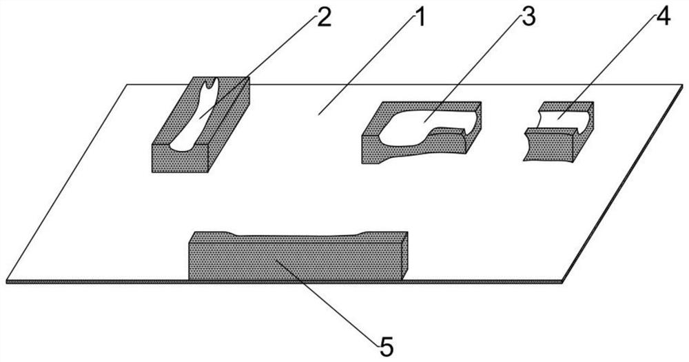
[0032] see figure 1 , figure 1 It is a structural schematic diagram of the posture frame for hip joint replacement in Example 1 of the present invention. The body posture frame for hip replacement in this embodiment includes a flexible base 1 with a width smaller than that of an operating bed and a hospital bed and protruding from the flexible base. 1 A plurality of bionic support modules on the upper surface, the upper surface and / or side wall of the bionic support modules are manufactured with bionic structures, and the bionic structures are processed according to the patient's standard body position information.

[0033] Specifically, the above-mentioned posture frame for hip joint replacement, the plurality of bionic support modules are used to support the standard lateral position, which includes an upper limb support module 2 and a back support module 5, and the upper limb support module 2 An upper limb bionic structure is manufactured on the upper surface, and a back b...

Embodiment 2

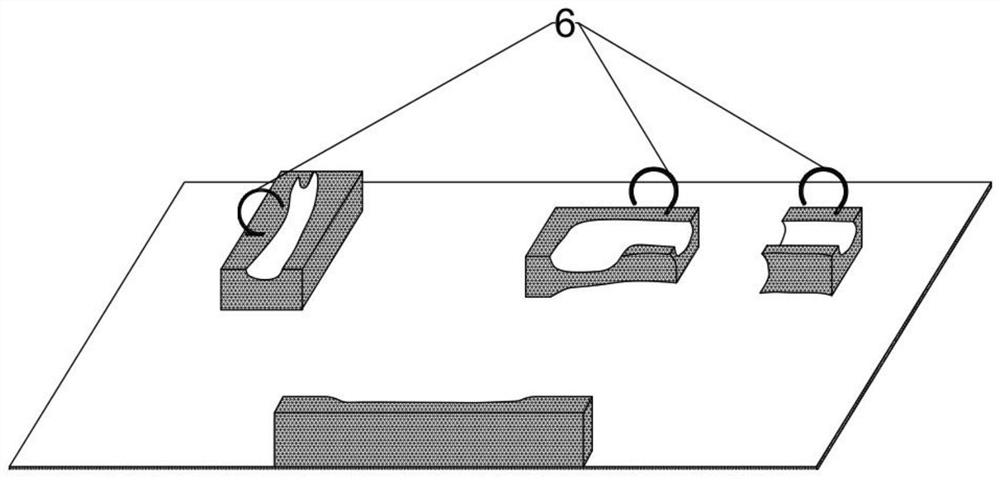
[0044] figure 2 It is the schematic diagram of the body position frame for hip replacement in this embodiment, and its scheme is actually a further improvement of the body position frame for hip replacement in Example 1. In this embodiment, in order to better restrain the patient's body position, The upper limb support module 2, the knee joint support module 3, and the calf or ankle support module 4 are all equipped with straps 6, which are used to assist in restraining human limbs.

[0045] The strap 6 in this embodiment is installed on the posture frame after the 3D printing is completed.

Embodiment 3

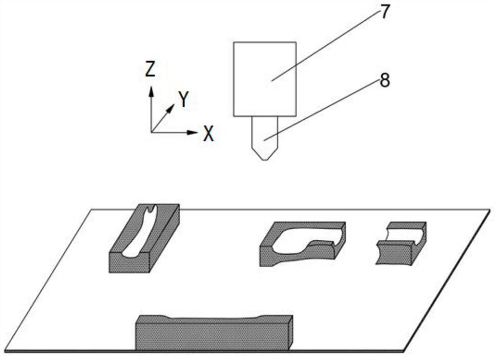
[0047] This embodiment is another design for the solution of growing multiple bionic support modules on the upper surface of the flexible substrate 1 by means of 3D printing in Example 1. Since FDM printing itself needs to design a substrate material, this solution directly select the existing flexible substrate 1 made of flexible breathable material as the printed substrate material, in this case, the process of printing the flexible substrate 1 layer by layer can be omitted in step 4, and it is not necessary in step 2 Add the 3D features of the flexible substrate 1 to the 3D digital model, where the flexible substrate 1 directly becomes the growth basis of the bionic support module. In this case, the material of the flexible substrate 1 may be different from the material of the bionic support module, but as long as The material of the flexible substrate 1 and the biomimetic support module can be easily fused (most commonly used polymer materials can be realized), which provid...


PUM


Abstract

The invention discloses a body position frame for hip replacement. The frame comprises a flexible base and a plurality of bionic supporting modules protruding out of the upper surface of the flexible base, and bionic structures are manufactured on the upper surfaces and / or the side wall faces of the bionic supporting modules, wherein the bionic structures are processed according to standard body position information of a patient. A manufacturing method of the body position frame is characterized in that the bionic supporting modules grow on the upper surface of the flexible substrate through a three-dimensional printing mode. According to the body position frame and the method, the upper limb supporting module, the back supporting module, the knee joint supporting module and the shank or ankle supporting module are scientifically partitioned, and the bionic structures on the modules are optimally arranged, so that the standard body position of the patient is limited, and huge workload of a doctor in a preoperative preparation stage and an operation can be greatly reduced; the three-dimensionally printed body position frame is not a stiff mechanical frame any more, but is a flexible environment-friendly printing material with a bionic outline, so that the discomfort of the patient is eliminated, and the body position frame can be continued to serve as a posture maintaining support in a rehabilitation stage; and a new customized medical mode is developed in hip replacement, and prospects are wide.

Description

technical field [0001] The invention relates to the technical field of medical aids and 3D printing, in particular to a body position frame for hip joint replacement and a manufacturing method thereof. Background technique [0002] Hip replacement is a commonly performed clinical operation. During the operation, the lower limbs are usually placed in a side-lying position and maintained at a reasonable angle, so as to clearly expose the acetabulum and reduce intraoperative interference. Because it is very difficult for the patient to maintain a fixed posture for a long time during the operation, multiple doctors are often needed to assist in correcting the posture during the operation, and the workload is heavy. Therefore, some auxiliary posture frames are used to carry out the operation clinically to reduce the workload of doctors. [0003] However, the most suitable posture and angle have a lot to do with the body shape of the individual patient, the length of the lower lim...

Claims


Application Information

Patent Timeline
Patent Type & Authority Applications(China)
IPC IPC(8): A61G13/00A61G13/12A61G7/065A61G7/07A61G7/075B29C64/386B29C64/118B33Y10/00B33Y50/00B33Y80/00
CPCA61G13/0081A61G13/1225A61G13/1235A61G13/1245A61G13/125A61G13/126A61G7/065A61G7/07A61G7/075B29C64/386B29C64/118B33Y10/00B33Y50/00B33Y80/00A61G2210/10Y02P10/25
Inventor 朴俊杰
Owner CHIFENG MUNICIPAL HOSPITAL
Why Eureka
Try Eureka