
Large vertical flue gas, air and pulverized coal pipeline array type flow measuring device

A flow measurement device and pulverized coal pipeline technology, which is applied in the direction of detecting fluid flow by measuring pressure difference, volume/mass flow generated by mechanical effects, etc., can solve problems such as frequent failures, complex design, manual dust removal, etc. Ash and clogging, solving measurement problems, and solving the effect of powder-laden airflow

Pending Publication Date: 2021-06-15
XIAN THERMAL POWER RES INST CO LTD
View PDF0 Cites 1 Cited by
  • Summary
  • Abstract
  • Description
  • Claims
  • Application Information

AI Technical Summary

Problems solved by technology

For the second type of problem, thermal power plants generally use array measurement devices for the measurement of powdery air flow in large-scale flue gas and pulverized coal pipelines. Array air volume measurement devices are very suitable for horizontal flues. Coal powder or smoke is not easy to accumulate. For vertical pipes, due to structural reasons, the current array flow measurement devices cannot solve the problem of ash accumulation and clogging. Even if some of them are blown with compressed air, maintenance personnel frequently blow and manually Dust cleaning, some are also designed as complex compressed air automatic back-purging devices, the design is complex, the cost is high, and the failures are frequent. Occurs, burying hidden dangers for the safe and economical operation of power plant boilers

Method used


Image

  • Large vertical flue gas, air and pulverized coal pipeline array type flow measuring device
  • Large vertical flue gas, air and pulverized coal pipeline array type flow measuring device
  • Large vertical flue gas, air and pulverized coal pipeline array type flow measuring device

Examples


Embodiment Construction

[0020] The present invention is described in further detail below in conjunction with accompanying drawing:

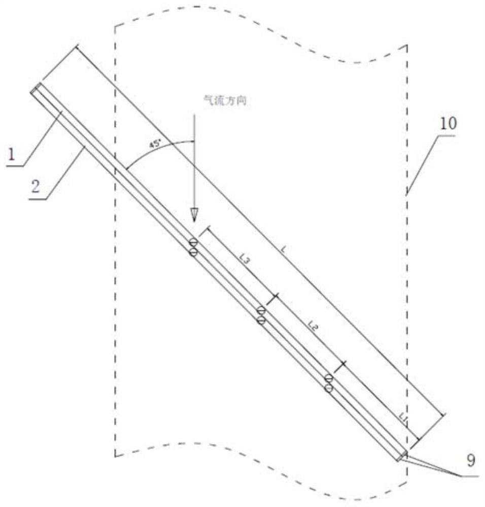
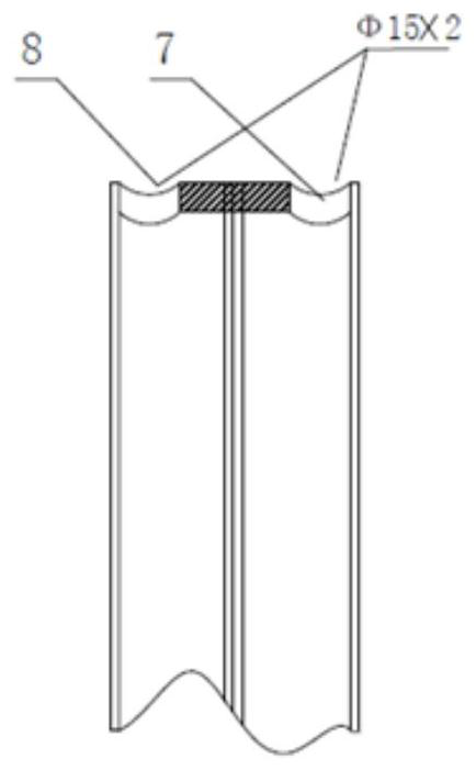
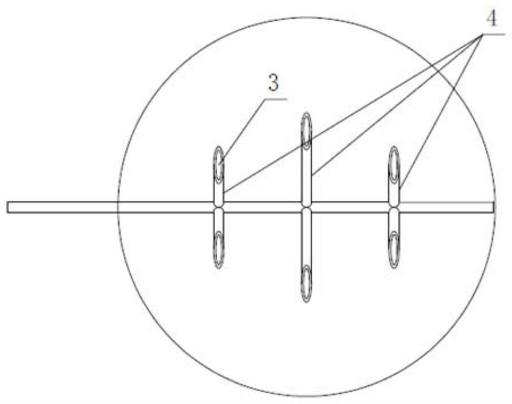
[0021] refer to Figure 1 to Figure 4 , the large-scale vertical flue gas pulverized coal pipeline array flow measuring device according to the present invention includes a dynamic pressure expansion buffer pipe 1, a static pressure expansion buffer pipe 2, a wedge type dynamic pressure sensor 3, a parallel static pressure sensor 4, a dynamic pressure transmission Pressure pipe 5, static pressure transmission pipe 6, dynamic pressure sampling hole 7, static pressure sampling hole 8 and ash release sealing plug 9; the front end of dynamic pressure expansion buffer pipe 1 and the upper end of static pressure expansion buffer pipe 2 are obliquely inserted into In the smoke wind pulverized coal pipeline 10, the lower end of the dynamic pressure expansion buffer pipe 1 and the lower end of the static pressure expansion buffer pipe 2 are closed, and each wedge type dynamic p...


PUM


Abstract

The invention discloses a large vertical flue gas, air and pulverized coal pipeline array type flow measuring device which is characterized in that a front end of a dynamic pressure expansion buffer pipe and an upper end of a static pressure expansion buffer pipe are obliquely inserted into a flue gas, air and pulverized coal pipeline, and a lower end of the dynamic pressure expansion buffer pipe and a lower end of the static pressure expansion buffer pipe are closed; wedge type dynamic pressure sensors are communicated with the dynamic pressure expansion buffer pipe, parallel static pressure sensors are communicated with the static pressure expansion buffer pipe, the wedge type dynamic pressure sensors and the parallel static pressure sensors are all located in a flue gas, air and pulverized coal pipeline, a dynamic pressure sampling hole is formed in an upper end of the dynamic pressure expansion buffer pipe, a static pressure sampling hole is formed in an upper end of the static pressure capacity expansion buffer pipe, the wedge type dynamic pressure sensors directly face the airflow direction in the flue gas, air and pulverized coal pipeline, the opening direction of the parallel static pressure sensors is parallel to the airflow direction in the flue gas, air and pulverized coal pipeline, and the device can effectively solve a problem of measurement of airflow with pulverized coal in a large vertical flue gas, air and pulverized coal pipeline.

Description

technical field [0001] The invention belongs to the technical field of power station boiler monitoring and control, and relates to a large-scale vertical flue gas pulverized coal pipeline array flow measuring device. Background technique [0002] The flow measurement of large flue gas pulverized coal pipelines in thermal power plants is related to the ratio of wind and coal in thermal power plants, the level of automation control, and safe and economical operation. So far, the measurement of powder-laden airflow has always been a major problem for power plants. To solve the measurement of powder-laden air flow, two types of problems must be solved first. The first type is the problem of anti-wear, anti-blocking, high temperature resistance and anti-corrosion. The second type is the problem of uneven distribution of flow velocity in the large-scale fume and pulverized coal pipeline. For the first type of problems, different media and different materials can be used to solve t...

Claims


Application Information

Patent Timeline
IPC IPC(8): G01F1/34
CPCG01F1/34
Inventor 武宝会司小飞黄钢英马百灵
Owner XIAN THERMAL POWER RES INST CO LTD
Learn More