Tool platform for steel structure machining
A steel structure and platform technology, which is applied in the field of tooling platforms for steel structure processing, can solve the problems of troublesome adjustment operations, time-consuming and labor-intensive adjustments, and inflexible adjustment methods, and achieve the effects of reducing labor intensity, convenient use, and simple adjustment methods
- Summary
- Abstract
- Description
- Claims
- Application Information
AI Technical Summary
Problems solved by technology
Method used
Image
Examples
example 1
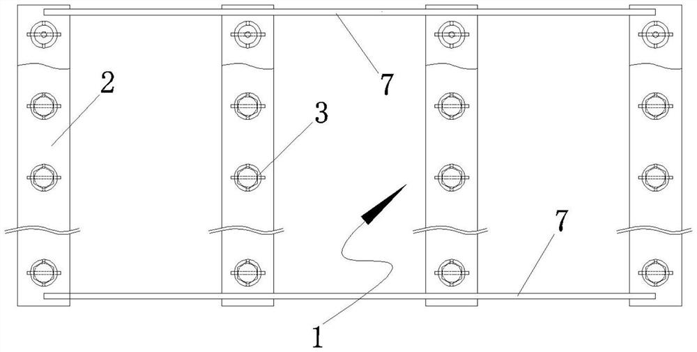
[0033] Example 1. This example 1 includes several tooling platform units 1 distributed side by side. The tooling platform unit 1 includes a base 2 and several adjustment mechanisms 3 arranged side by side and equidistant on the base 2 for adjusting the support height. The present invention is mainly composed of tooling platform units, several tooling platform units are distributed in parallel and equidistant, and the adjusting mechanism 3 is equidistantly distributed on the base 2 of the tooling platform unit 1, and the same tooling platform unit 1 can be adjusted through the adjusting mechanism 3 to adjust different The support height can meet the support requirements of special-shaped steel structure components. The adjustment method is simple and flexible.
example 2
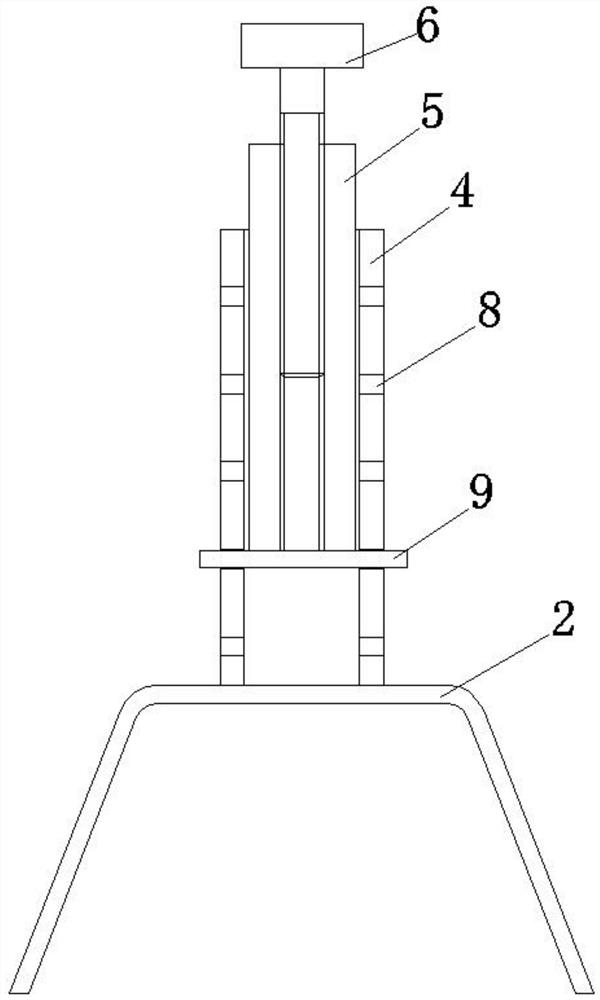
[0034] Example 2. This example 2 includes several tooling platform units 1 distributed side by side. The tooling platform unit 1 includes a base 2 and several adjustment mechanisms 3 arranged side by side and equidistant on the base 2 for adjusting the support height. The adjustment mechanism 3 includes a cylindrical outer seat 4 fixed on the base 2, an inner tube 5 sleeved in the outer seat 4 for adjusting the support height, and an adjusting bolt threaded in the inner tube 5 for fine-tuning the support height 6; The outer seat 4 is provided with a limit mechanism for adjusting the elevation of the inner tube 5 .
[0035] In Example 2, on the basis of Example 1, the structure of the adjustment mechanism 3 is optimally designed, and the adjustment is more convenient and flexible through the adjustment mechanism 3 composed of the outer seat 4, the inner tube 5, the adjustment bolt 6, and the limit mechanism. The structure is stable and the support performance is good.
example 3
[0036] Example 3. This example 3 includes several tooling platform units 1 distributed side by side. The tooling platform unit 1 includes a base 2 and several adjustment mechanisms 3 arranged side by side and equidistant on the base 2 for adjusting the support height. The adjustment mechanism 3 includes a cylindrical outer seat 4 fixed on the base 2, an inner tube 5 sleeved in the outer seat 4 for adjusting the support height, and an adjusting bolt threaded in the inner tube 5 for fine-tuning the support height 6; The outer seat 4 is provided with a limit mechanism for adjusting the elevation of the inner tube 5 . The limiting mechanism includes several pairs of pin through holes 8 equidistantly opened on the outer base 4 along the length direction of the outer base 4 , and adjusting pins 9 inserted into the through holes 8 to limit the adjustment of the inner tube 5 .
[0037] In Example 3, on the basis of Example 2, the structure of the limit mechanism is optimized. Through ...
PUM
 Abstract
Description
Claims
Application Information
 - R&D Engineer
- R&D Manager
- IP Professional
- Industry Leading Data Capabilities
- Powerful AI technology
- Patent DNA Extraction
Browse by: Latest US Patents, China's latest patents, Technical Efficacy Thesaurus, Application Domain, Technology Topic, Popular Technical Reports.
© 2024 PatSnap. All rights reserved.Legal|Privacy policy|Modern Slavery Act Transparency Statement|Sitemap|About US| Contact US: help@patsnap.com


