
L-band broom-shaped antenna

An L-band, broom-shaped technology, which is applied in the field of L-band broom-shaped antennas, can solve the problems of insufficient beam phase distribution, insufficient beam width in azimuth plane, and large beam width in elevation plane, etc., to achieve high beam phase flatness and improve Performance vs Test Efficiency, Effect of Low Sidelobe Levels

Pending Publication Date: 2021-06-11
SHENYANG AIRCRAFT DESIGN INST AVIATION IND CORP OF CHINA
View PDF5 Cites 0 Cited by
  • Summary
  • Abstract
  • Description
  • Claims
  • Application Information

AI Technical Summary

Problems solved by technology

[0009] At present, commonly used measurement antennas include square / round mouth horn antennas, corrugated horn antennas, and ridge waveguide horn antennas. These antennas have the characteristics of broadband, high gain, and low sidelobes. Insufficient surface beam width, too large elevation surface beam width, insufficient flatness of beam phase distribution, and large antenna size. Therefore, there is an urgent need for a measurement antenna suitable for the performance requirements of the indoor near-field scattering characteristics of aircraft targets.

Method used


Image

  • L-band broom-shaped antenna
  • L-band broom-shaped antenna
  • L-band broom-shaped antenna

Examples


Embodiment Construction

[0024] In order to make the objectives, technical solutions and advantages of the implementation of the application clearer, the technical solutions in the implementation modes of the application will be described in more detail below with reference to the drawings in the implementation modes of the application. In the drawings, the same or similar reference numerals denote the same or similar elements or elements having the same or similar functions throughout. The described embodiments are some, but not all, embodiments of the present application. The embodiments described below by referring to the figures are exemplary and are intended to explain the present application, and should not be construed as limiting the present application. Based on the implementation manners in this application, all other implementation manners obtained by persons of ordinary skill in the art without creative efforts fall within the scope of protection of this application. Embodiments of the pr...


PUM


Abstract

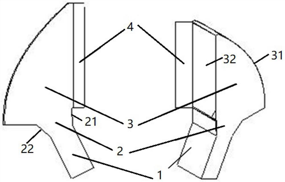
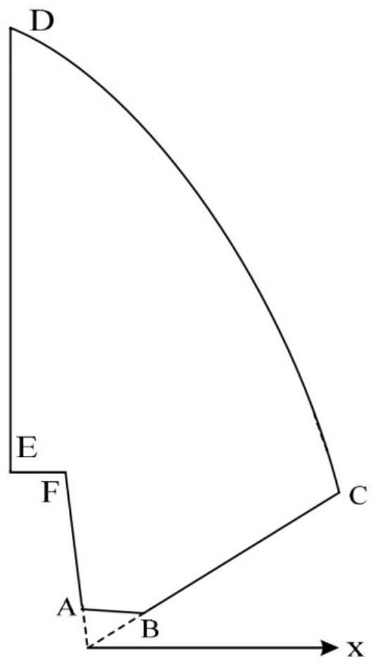
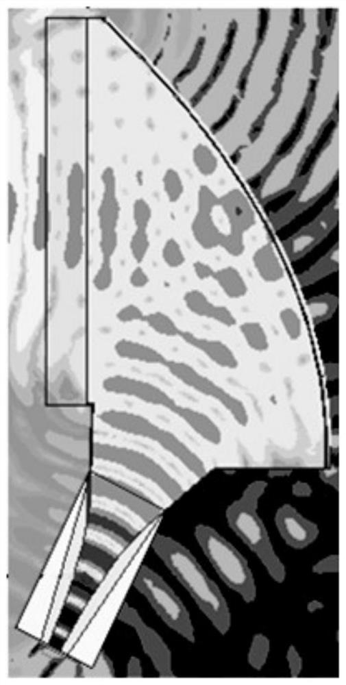
The invention belongs to the technical field of antenna design, and particularly relates to an L-band broom-shaped antenna. The antenna comprises a ridge waveguide feed source (1), a feed source reflection cavity transition structure (2) and a parabolic reflection cavity (3), wherein a ridge-shaped metal sheet extending along a broadside wave band wall is arranged in the ridge waveguide feed source (1); the feed source reflection cavity transition structure (2) is arranged at an outlet of the ridge waveguide feed source (1) and extends in a horn mouth shape, and smooth transition between the feed source reflection cavity transition structure (2) and the parabolic reflection cavity (3) is achieved. The parabolic reflection cavity (3) comprises a parabolic reflection cavity surface (31) and a radiation outlet (32) opposite to the parabolic reflection cavity surface, and beam reflection is carried out through the parabolic reflection cavity surface (31). The antenna has the advantages of wide directional diagram azimuth plane wave beam, narrow pitching plane wave beam, low side lobe level, high wave beam phase flatness and the like, the use requirement and the performance requirement of aircraft target near-field scattering characteristic detection on the measurement antenna are met, and the performance and the test efficiency of a test system are improved.

Description

technical field [0001] The application belongs to the technical field of antenna design, in particular to an L-band broom antenna. Background technique [0002] Target scattering characteristics are one of the core performance indicators of aviation weaponry. Accurately knowing the scattering characteristics of targets is a prerequisite for the development of the entire process of aviation weapon equipment design, manufacturing, and testing. essential factor. [0003] The detection methods of aircraft target scattering characteristics include compact field darkroom, outdoor test field, air dynamic flight and indoor near-field detection. Among them, the near-field test is mainly based on the inspection of the actual aircraft leaving the factory and in service, while taking into account equipment and components. The near-field measurement method is used indoors to test the scattering characteristics of the installed stealth aircraft target in azimuth, elevation, polarization...

Claims


Application Information

Patent Timeline
Patent Type & Authority Applications(China)
IPC IPC(8): H01Q1/36H01Q1/50H01Q15/16H01Q19/12G01S7/41
CPCH01Q1/36H01Q1/50H01Q15/16H01Q19/12G01S7/411
Inventor 张澎张翀刘迟
Owner SHENYANG AIRCRAFT DESIGN INST AVIATION IND CORP OF CHINA
Learn More