Eureka AIR delivers breakthrough ideas for toughest innovation challenges, trusted by R&D personnel around the world.

Reburning denitration biogas treatment system of garbage incineration grate furnace

A waste incinerator and biogas technology, applied in incinerators, non-combustible liquid/gas transportation, combustion methods, etc., can solve the problems of increased NOx emission concentration, energy waste, and temperature rise, and reduce the amount of ammonia injection , reduce the amount of ammonia injection, improve the effect of combustion efficiency

Pending Publication Date: 2021-06-11
SHANGHAI SUS ENVIRONMENT
View PDF12 Cites 1 Cited by
  • Summary
  • Abstract
  • Description
  • Claims
  • Application Information

AI Technical Summary

Problems solved by technology

[0002] The leachate treatment station is a conventional facility for waste incineration plants. The leachate will produce a large amount of biogas and other flammable gases after anaerobic fermentation. The biogas has a high calorific value, which can reach 24MJ / Nm 3 , but the general incineration plant will burn the biogas through the torch, resulting in energy waste
In recent years, most waste incineration plants have installed biogas burners, through which the biogas is incinerated into the furnace, so that the heat of the biogas can be fully utilized, but the combustion of biogas into the furnace will cause the temperature in the furnace to rise, resulting in coking and NOx emissions in the furnace Increased risk of elevated concentrations

Method used


Image

  • Reburning denitration biogas treatment system of garbage incineration grate furnace
  • Reburning denitration biogas treatment system of garbage incineration grate furnace

Examples


Embodiment Construction

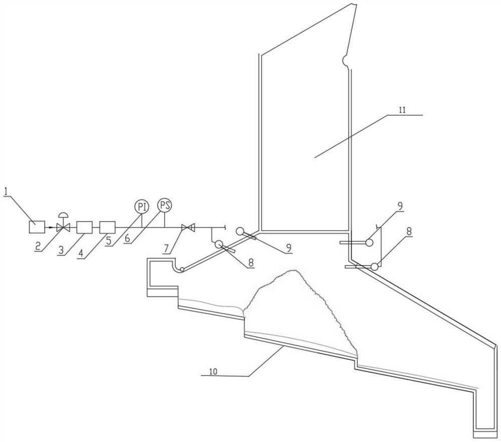
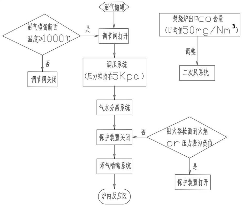
[0018] Such as figure 1 As shown, the incinerator is a stepped furnace (10) with inclination, and the front and rear arch and side walls, the flue (11) is composed, and the biogas return nozzle (8) and the secondary wind nozzle (9) are arranged before and after arch. Location, the biogas return nozzle (8) is disposed at the upper and rear arches, and the front arch region is disposed at a 20 ° arrangement, and the rear arch region is disposed. Biogas take the anaerobic fermentation system, output from the biogas storage tank (1), the flow rate is controlled by the pneumatic regulator (2), the pressure regulating system (3) is to maintain system pressure, enhance gas mixed disturbance, improve mixing If the gas stop time is provided, the gas-water separation system (4) can separate moisture in the biogas, pressure gauge (5), pressure switch (6) and fire detector (7) prevent flue gas or flame from entering the biogas pipe system. When the biogas nozzle section temperature reaches 10...


PUM


Abstract

The invention is suitable for the field of household garbage incineration, and relates to a reburning denitration biogas treatment system of a garbage incineration grate furnace. The reburning denitration biogas treatment system is composed of hearth biogas back-spraying nozzles, a secondary air nozzle, a biogas conveying device, a pneumatic control valve, a pressure switch, a flame retardant device, a grate and a flue; the biogas back-spraying nozzles are arranged in front and back arch areas, and the inclination angles of the nozzles are arranged according to a hearth structure, so that flue gas is fully mixed, and the flue gas retention time is prolonged; the secondary air nozzle is arranged at the upper part of the biogas back-spraying nozzles so as to supplement oxygen to enable the combustible gas to be completely combusted; and biogas is taken from a leachate anaerobic fermentation system and is conveyed into the furnace through the biogas conveying device. According to the reburning denitration biogas treatment system, the biogas can be treated by spraying the biogas into the high-temperature oxygen-deficient area of the hearth, and meanwhile, NOx is reduced into N2; the system has the functions of adjusting the amount of biogas entering the furnace and protecting the safety of the whole system through a biogas system protection device; and according to the reburning denitration biogas treatment system, combustible substances can be completely combusted by supplementing secondary air.

Description

Technical field [0001] The present invention is suitable for the field of domestic waste incineration, especially a waste incinerator, re-burning dermal treatment biogas system. Background technique [0002] The leachate treatment station is a routine configuration facility of the waste incineration plant, and the leachate will produce a large amount of biogas such as a large amount of biogas, which can reach 24MJ / NM by anaerobic fermentation. 3 However, the general incinerator will burn the biogas through the torch, resulting in energy waste. In recent years, most waste incineration plants will set biogas burners, biogas into incinerate through the burner, so that the heat of biogas is fully utilized, but the boggle into the furnace will cause increase in the furnace, resulting in furnace coking and NOx emissions Risk of concentration increases. Inventive content [0003] Re-combustion reintegration is produced by mixing with NOx mixed with NOx in a regenerative atmosphere. 2...

Claims


Application Information

Patent Timeline
Patent Type & Authority Applications(China)
IPC IPC(8): F23G5/00F23G5/44F23G5/50F23L9/00
CPCF23G5/00F23G5/44F23G5/50F23L9/00
Inventor 龙吉生单福朋李建平严浩文王玮余国涛张坡袁旗斌乔旭贾敏华
Owner SHANGHAI SUS ENVIRONMENT
Why Eureka
Eureka Blog
Learn More