Ship exhaust gas treatment system

A waste gas treatment and ship technology, which is applied in the field of ship waste gas treatment system, can solve the problems of bag opening, rigid collision, corrosion of buildings, etc., and achieve the effect of increasing tension, facilitating deformation, and improving cushioning and shock absorption

Inactive Publication Date: 2021-06-08
费红泉
View PDF0 Cites 0 Cited by
  • Summary
  • Abstract
  • Description
  • Claims
  • Application Information

AI Technical Summary

Problems solved by technology

Excessive emissions of sulfur oxides and nitrogen oxides have led to large-scale acid rain and smog in my country, severely corroded buildings, and damaged the ecological environment. The resulting greenhouse effect and ozone layer destruction are even more threatening to human survival; existing ship exhaust The treatment system will adopt two desulfurization methods: wet method and dry method. When adding desulfurization materials in bags, the plugging rod is used to limit the connection between the feed channel and the bag mouth. Once the plugging rod is affected by different The amount of desulfurization material pressed will open with different strengths, so that the plugging rod will rigidly collide with the inner wall of the feeding channel, and then swing back and forth to drag the folded edge of the bottom edge of the bag, causing the bag to turn outward and turn up The phenomenon makes the material scattered outside the feeding channel, reducing the efficiency of the system's exhaust gas treatment

Method used


Image

  • Ship exhaust gas treatment system
  • Ship exhaust gas treatment system
  • Ship exhaust gas treatment system

Examples


Embodiment 1

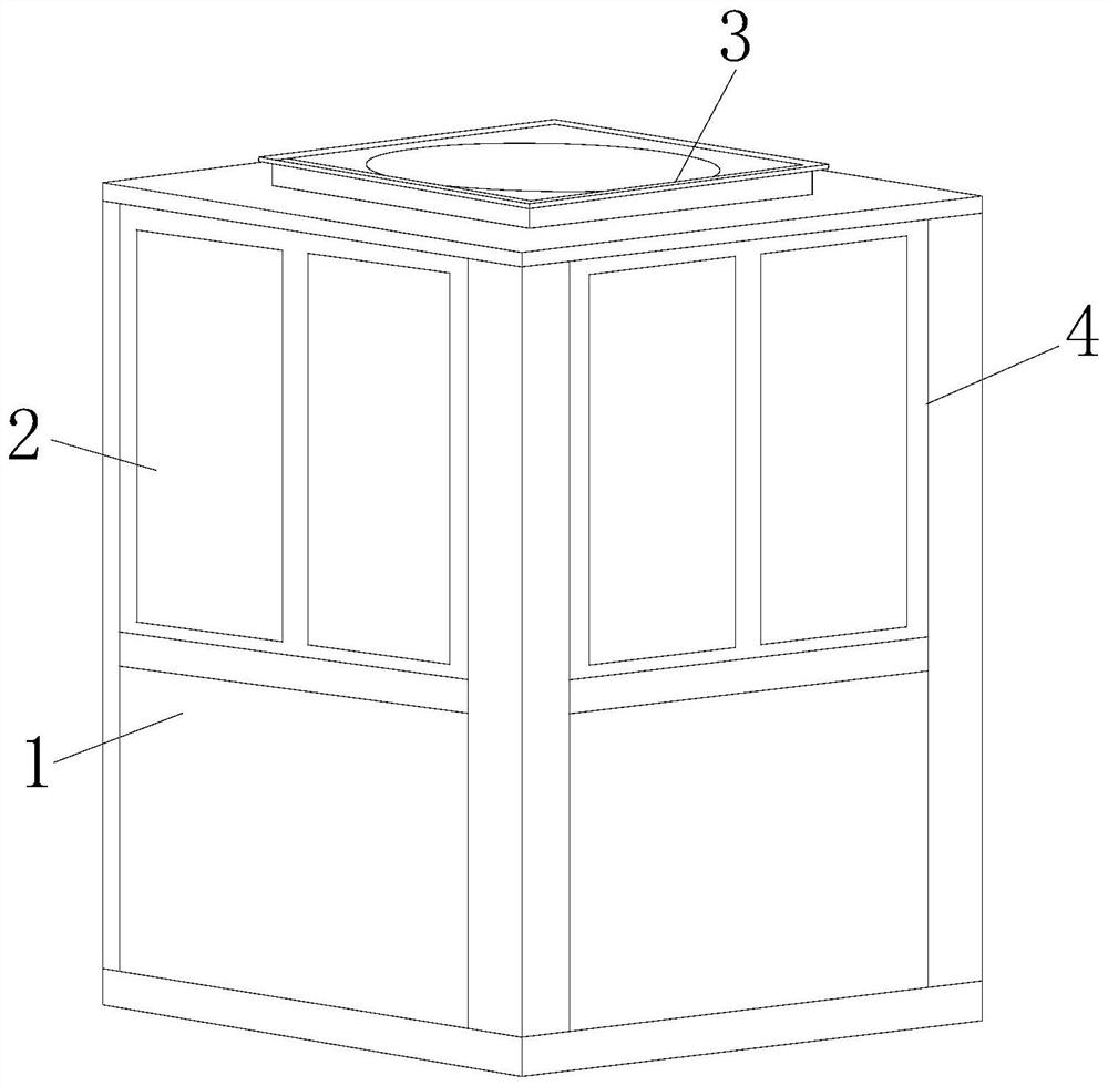
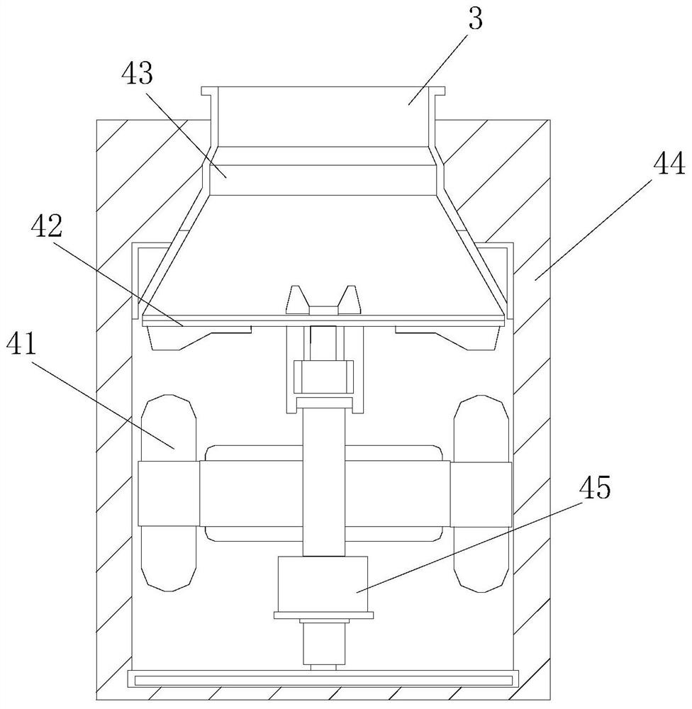
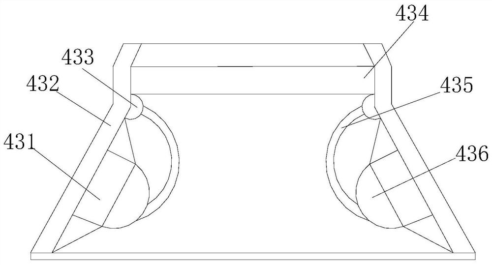
[0028] Such as Figure 1-Figure 4 As shown, the present invention provides a ship exhaust gas treatment system, the structure of which includes a base 1, an exhaust port 2, a top cover 3, and a main body 4. The base 1 and the exhaust port 2 are fixedly connected to the bottom and surroundings of the main body 4, respectively. The top of the main body 4 is welded with a top cover 3, and the main body 4 includes a processing machine 41, an equalizer 42, a feed channel 43, a housing 44, and a driving body 45. Between the processing machine 41 and the driving body 45 Cooperate in an electrically connected manner, the equalizing channel 42 is fixedly connected to the bottom of the feed channel 43, the feed channel 43 is installed inside the housing 44, and the top is welded to the bottom of the top cover 3, and the feed channel 43 is connected to the bottom of the top cover 3 by welding. The material channel 43 includes a supporting plate 431, an inner channel 432, a rotating shaft...

Embodiment 2

[0030] Such as Figure 5-Figure 8As shown, on the basis of Embodiment 1, the present invention combines the mutual cooperation of the following structural components. The buffer frame 362 includes a touch pad 621, a push plate 622, an elastic member 623, a moving rod 624, and a bucket 625. The tip of the contact pad 621 is embedded and connected inside the inner support part 361, and its arc surface is fixedly connected with a moving rod 624 and a push plate 622. There are two moving rods 624, which are respectively welded and connected to the elastic member 623. On both sides, one side of the push plate 622 is inserted and connected with a spreading bucket 625, and the elastic member 623 is in the shape of an inverted arch bridge, the middle part of which will sink and bend to indirect contact with the middle part of the inner support part 361, and the creases at both ends will Transition fit with the spreading bucket 625, so that the corrugated structure on the other side of...


PUM


Abstract

The invention discloses a ship exhaust gas treatment system which structurally comprises a base, gas outlets, a top cover and a main body, wherein the base and the gas outlets are connected to the bottom and the four sides of the main body; and the main body is connected with the top cover. Power assisting assemblies are provided with contact buffering frames and clamping structures, and the contact buffering frames and the clamping structures are utilized to cooperate through running-in channels. When plugging rods are opened downwards, the plugging rods cause impacts first and are frictionally dragged along the running-in channels, and the overall widths of the contact buffering frames are shortened, so that the contact buffering frames are squeezed and compressed together. The extension enables the plugging rods to be transitionally lifted into the clamping structures so as to perform forced position fixing. Therefore, secondary weakening of impact forces is achieved; the buffering and shock absorption effects are improved; and the plugging rods are prevented from swinging back and forth.

Description

technical field [0001] The invention relates to the field of exhaust gas discharge, in particular to a ship exhaust gas treatment system. Background technique [0002] Marine diesel engine flue gas contains a large number of air pollutants, the vast majority of which are particulate matter, sulfur dioxide, nitrogen oxides and carbon monoxide. Excessive emissions of sulfur oxides and nitrogen oxides have led to large-scale acid rain and smog in my country, severely corroded buildings, and damaged the ecological environment. The resulting greenhouse effect and ozone layer destruction are even more threatening to human survival; existing ship exhaust The treatment system will adopt two desulfurization methods: wet method and dry method. When adding desulfurization materials with bags, the plugging rod is used to limit the connection between the feed channel and the bag mouth. Once the plugging rod is affected by different The dose of desulfurization material is pressed, and it w...

Claims


Application Information

Patent Timeline
IPC IPC(8): B65G65/40B01D53/92B01D53/50
CPCB01D53/50B01D53/92B01D2258/012B65G65/40
Inventor 费红泉
Owner 费红泉
Why Eureka
Try Eureka