
Inorganic nonmetal pipe cutting equipment

A kind of pipe cutting equipment, inorganic non-metal technology, applied in the direction of stone processing equipment, stone processing tools, work accessories, etc.

Inactive Publication Date: 2021-06-08
庄福全
View PDF0 Cites 0 Cited by
  • Summary
  • Abstract
  • Description
  • Claims
  • Application Information

AI Technical Summary

Problems solved by technology

[0006] In order to solve the above-mentioned technology when cutting the hollow-textured pipe body stacked by ceramic materials, in the process of cutting the edge of the ceramic pipe material, each texture is intertwined at a position, and it is easier to avoid the vibration generated during cutting. cracked problem

Method used


Image

  • Inorganic nonmetal pipe cutting equipment
  • Inorganic nonmetal pipe cutting equipment
  • Inorganic nonmetal pipe cutting equipment

Examples


Embodiment 1

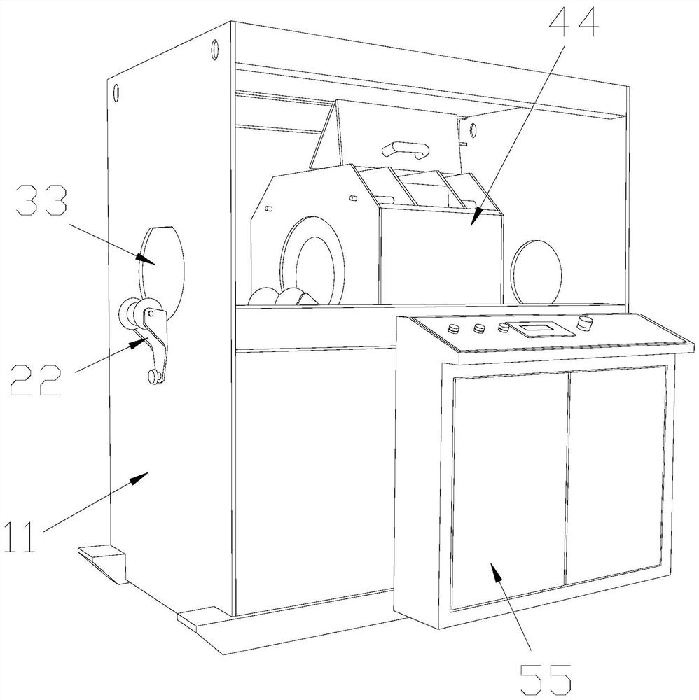
[0032] as attached figure 1 To attach Figure 6 Shown:

[0033] The present invention provides an inorganic non-metallic pipe cutting device, the structure of which includes a support plate 11, a transport wheel 22, an insertion port 33, a cutting box 44, and a control box 55. The insertion port 33 and the support plate 11 are an integrated structure. The transportation wheels 22 are installed on the outer surface of the support plates 11 , the cutting box 44 is fixedly installed between the support plates 11 , and the control box 55 is welded on the outer surface of the support plates 11 .

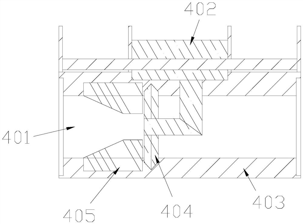
[0034] The cutting box 44 includes an insertion channel 401, a cutting control box 402, an outer limit case 403, a cutting piece 404, and an abutment ring 405. The insertion channel 401 runs through the outer limit case 403, and the abutment ring 405 is installed Inserted inside the channel 401, the cutting blade 404 and the cutting control box 402 are an integrated structure.

[0035]...

Embodiment 2

[0042] as attached Figure 7 to attach Figure 9 Shown:

[0043] Wherein, the elastic ring 512 includes a protruding support block x11, an inner spring plate x12, and an adhesive layer x13, the inner elastic plate x12 is embedded inside the adhesive layer x13, and the outer surface of the adhesive layer x13 is equipped with a protruding support block x11, so The inner elastic plate x12 itself is made of elastic material and distributed symmetrically. There are four protrusions x11. The rubber layer x13 is made of rubber material. When the overall force is applied to the rubber layer x13, it will Appropriately deformed, the protrusion x11 allows the outer layer to have a certain undulation range, which can better resist the textured surface, and the inner elastic plate x12 continues to maintain a state of expansion, and will only bend when a force is applied.

[0044] Wherein, the protruding block x11 includes a header m11, an arc m12, and an elastic strip m13. The header m11...


PUM


Abstract

The invention discloses inorganic nonmetal pipe cutting equipment. The inorganic nonmetal pipe cutting equipment structurally comprises supporting plates, conveying wheels, a placement opening, a cutting box and a control box, the placement opening and the supporting plates are of an integrated structure, the conveying wheels are installed on the outer surfaces of the supporting plates, and the cutting box is fixedly installed between the supporting plates. An abutting rubber body of an abutting ring continuously abuts against the surface of a pipe, the surface of a ceramic pipe is provided with uneven textures, protruding blocks can increase the abutting friction position of the protruding blocks, the protruding blocks can better abut against the surface of the textures in gaps due to distribution of the protruding blocks, the soft layer made of rubber wraps the ceramic pipe, the vibration range of the ceramic pipe is reduced, rubber wrapping and consolidating are carried out on the cut peripheral portion, excessive vibration is prevent, and an inner elastic plate can properly keep the elasticity and the shape of the inner elastic plate, so that the outer layer has a certain fluctuation range and can better abut against the surface of the textures, surface abutting adjustment can be conducted on the ceramic texture pipe when the ceramic texture pipe is cut, and vibration of the ceramic texture pipe is further prevented.

Description

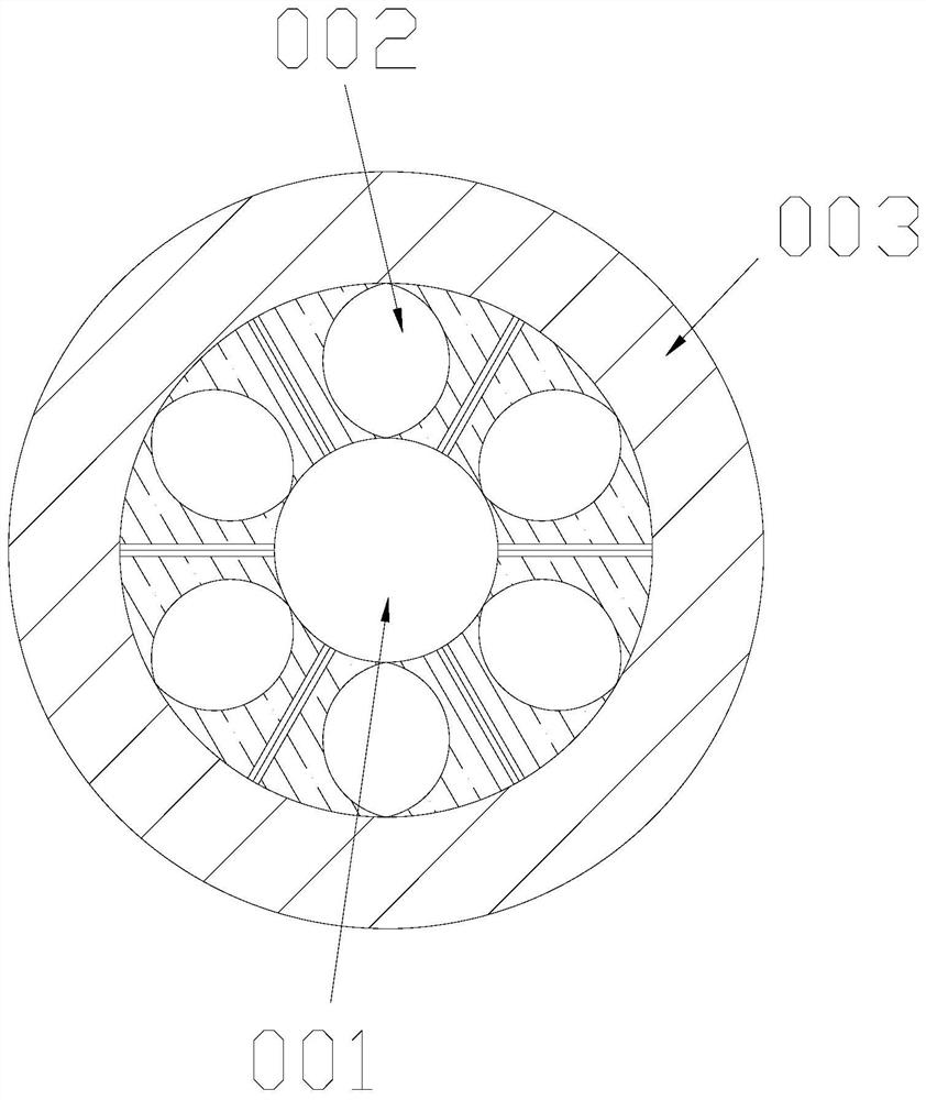
technical field [0001] The invention belongs to the field of inorganic non-metallic material equipment, and more specifically relates to an inorganic non-metallic pipe material cutting equipment. Background technique [0002] Ceramic pipes in inorganic non-metallic materials are composed of multiple strands of ceramic strips interwoven around a cylinder to form a textured ceramic pipe. After it is fired to form, it needs to be adjusted and cut in length so that it can be cut according to the required length. . [0003] Based on above-mentioned inventor's discovery, existing inorganic non-metallic pipe material cutting equipment mainly has the following deficiencies, such as: [0004] When cutting the hollow texture pipe body stacked by ceramic materials, in the process of cutting the edge of the ceramic pipe, each texture has a position where each texture is intertwined, and it is easier to break away from the vibration generated during cutting. [0005] Therefore need to ...

Claims


Application Information

Patent Timeline
Patent Type & Authority Applications(China)
IPC IPC(8): B28D7/04B28D1/24
CPCB28D1/24B28D7/04
Inventor 庄福全
Owner 庄福全
Learn More