Eureka AIR delivers breakthrough ideas for toughest innovation challenges, trusted by R&D personnel around the world.

Roller conveying track and roller machining equipment applying same

A conveying channel and roller technology, which is applied in metal processing equipment, grinding/polishing equipment, machine tools suitable for grinding workpiece planes, etc. Effect

Active Publication Date: 2021-06-08
宁波海亚特滚子有限公司
View PDF11 Cites 0 Cited by
  • Summary
  • Abstract
  • Description
  • Claims
  • Application Information

AI Technical Summary

Problems solved by technology

[0004] However, in the actual application environment, when it is applied to a centerless grinding machine, due to the difference in the size of the processed rollers, the blade needs to be pressed according to the need to be adjusted
However, the inventors found that with the adjustment of the knife plate, the position of the discharge port of the centerless grinder will change greatly
The traditional guide tube is usually only fixed on the centerless grinder frame through a simple simple bracket, and its feed inlet is relatively fixed, so it cannot be better adapted through the same guide tube.

Method used


Image

  • Roller conveying track and roller machining equipment applying same
  • Roller conveying track and roller machining equipment applying same
  • Roller conveying track and roller machining equipment applying same

Examples


Embodiment Construction

[0037] The following is attached Figure 1-6 The application is described in further detail.

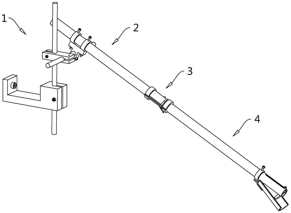
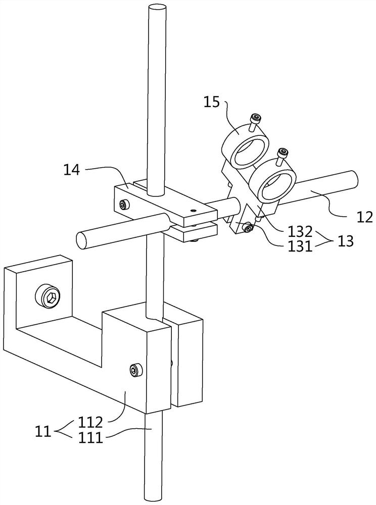
[0038] The embodiment of the present application discloses a roller conveyor. refer to figure 1The roller conveying path includes an adjusting support 1 and a conveying pipe arranged on the adjusting support 1. The adjusting support 1 can adjust the height of the conveying pipe and the inclination angle relative to the ground, and then adapt to rollers with different discharge heights. sub-processing equipment. The conveying pipe includes a receiving section 2, a transition pipe 3 and a guiding conveying section 4 arranged in sequence along its extension direction. The receiving section 2 is arranged on the adjusting support 1, and the transition pipe 3 is rotatably connected between the receiving section 2 and the guiding conveying section 4. , and the receiving section 2 remains relatively fixed with the guiding section 4 all the time. The transition pipe 3 rotates around its a...


PUM


Abstract

The invention relates to a roller conveying track and roller machining equipment applying the same. The roller conveying track comprises an adjusting support and a conveying pipe arranged on the adjusting support, the adjusting support comprises a supporting seat, a connecting rod and a fixing seat which are connected with one another, and the fixing seat is in sliding connection with the conveying pipe; and the connecting rod is horizontally arranged, and the fixing seat can rotate by taking the axis of the connecting rod as the axis. The roller conveying track has the effect of conveniently adapting to roller machining equipment with different discharging heights, and meanwhile can stably and efficiently remove waste produced by the roller machining equipment in the debugging stage .

Description

technical field [0001] The present application relates to the field of roller processing equipment, in particular to a roller conveyor and roller processing equipment using the roller conveyor. Background technique [0002] The roller is a common rolling element in a type of roller bearing. Its shape is generally cylindrical. When it is applied to a tapered roller bearing or a spherical roller bearing, the diameter of the two ends of the roller will vary. A certain difference, so that the outer peripheral wall of the roller has a certain slope. [0003] Today's rollers usually use grinding equipment such as end grinders and centerless grinders to finish the rollers, and workers usually set a guide material at the discharge port of the roller processing equipment to guide the rollers to be unloaded. Tubes, so that the rollers can be guided by the guide tubes to realize unloading or input to the next-level processing equipment. [0004] However, in the actual application env...

Claims


Application Information

Patent Timeline
Patent Type & Authority Applications(China)
IPC IPC(8): B24B5/35B24B5/22B24B7/16B24B7/17
CPCB24B5/35B24B5/22B24B7/16B24B7/17
Inventor 陈彬
Owner 宁波海亚特滚子有限公司
Why Eureka
Eureka Blog
Learn More