
Ambidextrously operated bolt catch assembly

a technology of ambidextrous control and bolt catch, which is applied in the field of firearms, can solve the problems of inability to consider mechanisms truly ambidextrous, no mechanism is provided on the right side of the receiver for the user to retain, and the control is critical for ergonomic and ambidextrous design

Active Publication Date: 2012-07-05
LWRC INTERNATIONAL
View PDF7 Cites 92 Cited by
  • Summary
  • Abstract
  • Description
  • Claims
  • Application Information

AI Technical Summary

Benefits of technology

[0013]In view of the foregoing, one object of the present invention is to overcome the difficulties encountered by left-handed shooters when operating conventionally designed automatic weapons having a lever for operating a bolt catch assembly only on the right side of the weapon.
[0019]It is yet another object of the invention to provide a bolt catch assembly that is not complex in structure and which can be manufactured at reasonable cost but yet efficiently allows both right and left-handed shooters to operate the bolt catch assembly to both restrain and release the bolt carrier group without moving out of the firing position.
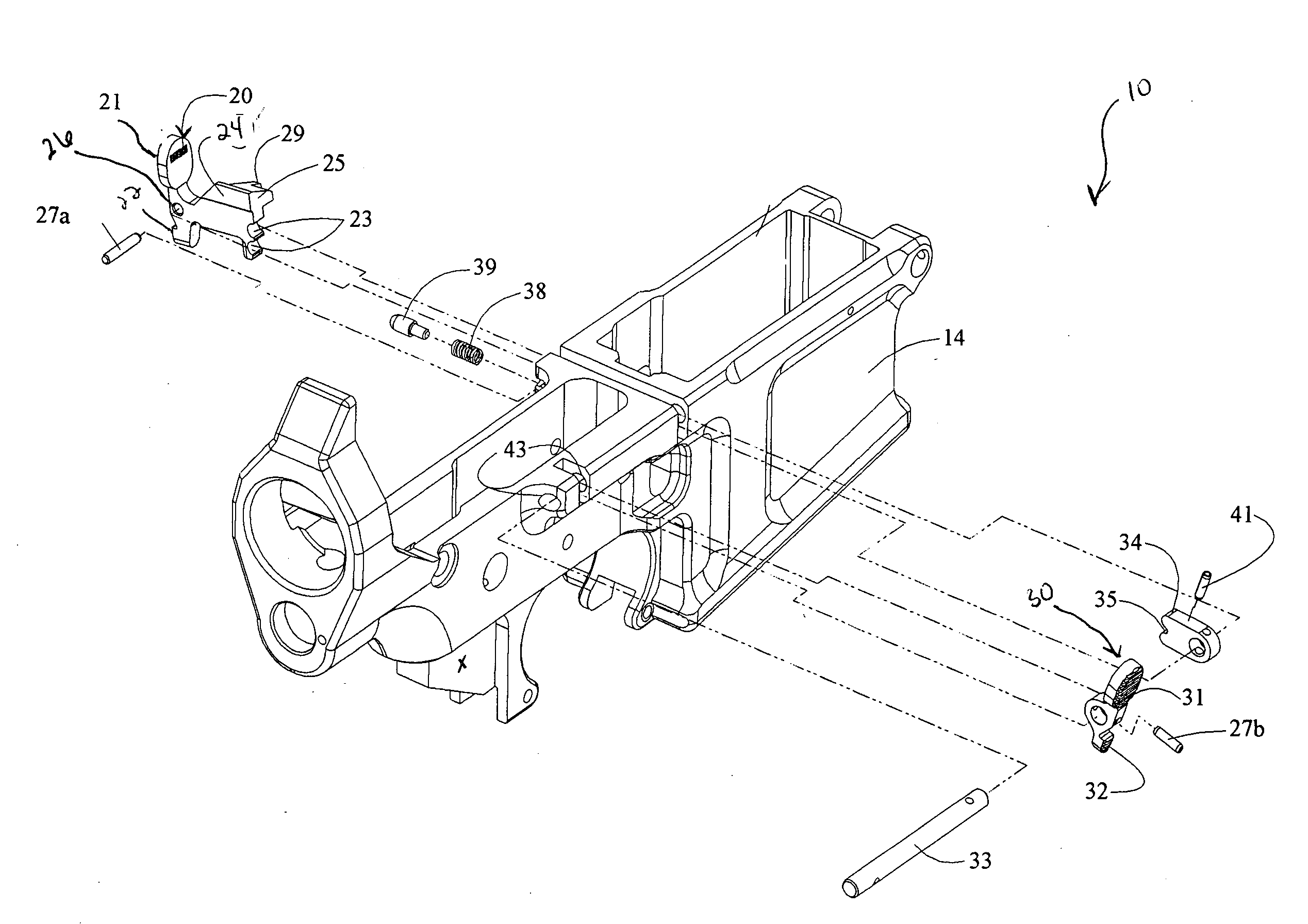
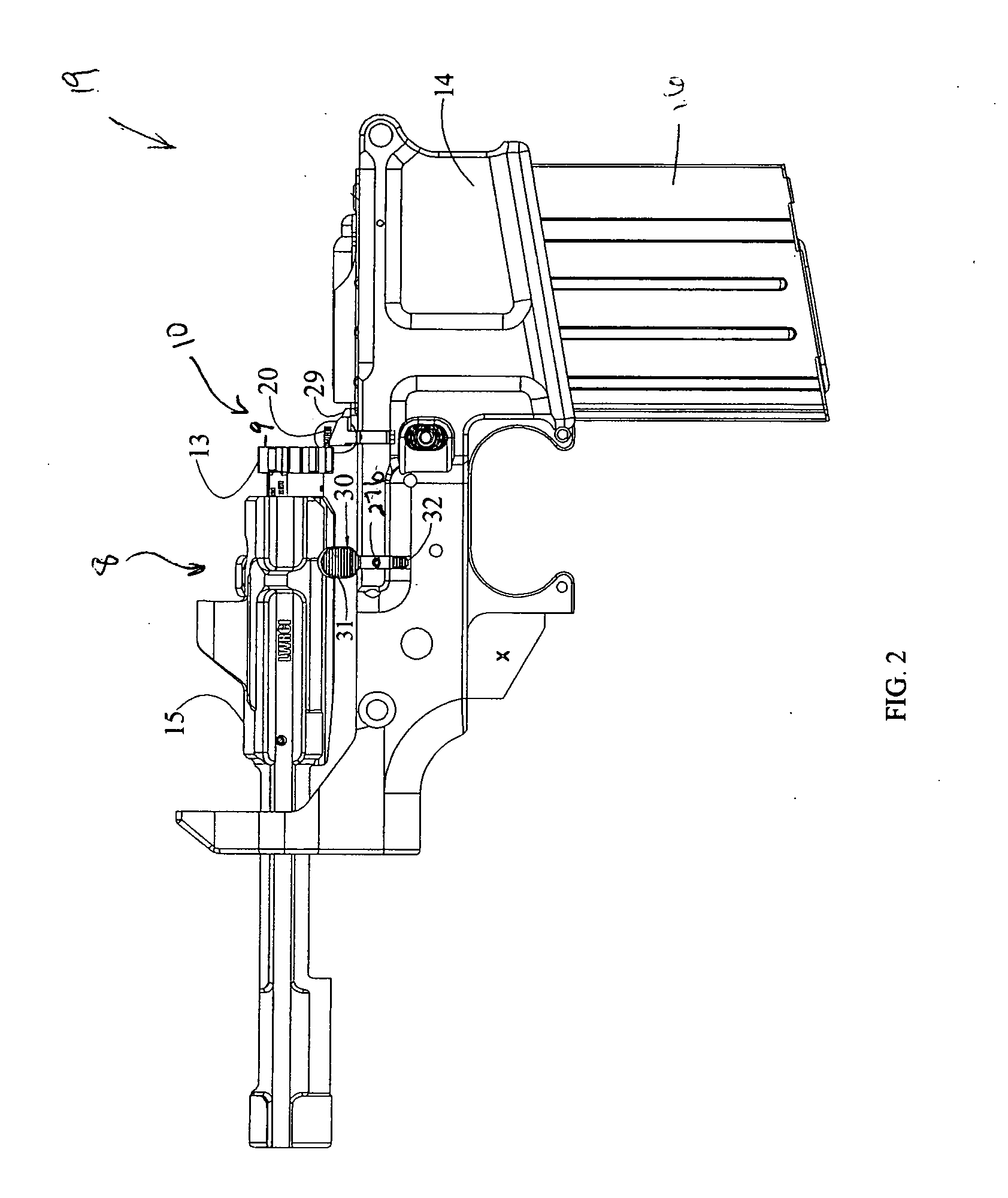
[0020]In accordance with these and other objects, the present invention is directed to a fast, efficient and ambidextrous bolt catch assembly that allows the user to both release and restrain the bolt carrier group of an autoloading firearm designed to receive detachable box magazines. The bolt catch assembly according to the present invention includes a primary bolt catch operating lever in the standard position found on the left side of the receiver, as in the M16 series of firearms, and a secondary bolt catch operating lever, in operational contact with the primary lever, placed on the right side of the receiver above the trigger group. The primary bolt catch operating lever includes a pivotally movable body having a bolt engagement leg and an engagement surface. The secondary bolt catch operating lever is connected via a rotating shaft to a lift arm with a coupling element complementary to the engagement surface. The coupling element is operationally coupled with the engagement surface on the body of the primary bolt catch operating lever so that movement of either operating lever serves to vertically displace the bolt engagement leg of the bolt catch assembly between the locked or displaced position, and the unlocked or static position.

Problems solved by technology

As such, ergonomic and ambidextrously designed controls can be critical.
However, no mechanism is provided on the right side of the receiver for the user to retain and release the bolt carrier group from the locked-back position.
In consideration of this fact alone these mechanisms cannot be considered truly ambidextrous.
Unfortunately the various mechanisms used, for example in the M16 family of firearms, to secure the bolt carrier group in the open, or locked-back, position are primarily designed for right-handed shooters.
While a left-handed shooter can operate the mechanism, the procedure is often slower and requires the use of a certain amount of the user's concentration to look at the firearm.
While the time required may be less than a second, an enemy action may occur during a critical time, thereby dangerously distracting the shooter.
When soldiers find themselves in a situation that requires target engagement around corners or in tight confines, it often becomes necessary to operate the weapon with the “weak hand” or the hand with which the shooter typically does not perform fine motor functions.
The disadvantage of this operation is that the user is required to move out of the firing position, thereby delaying his response to an enemy action.
Releasing the bolt using the operating lever of the bolt catch assembly eliminates the need to use the charging handle for this purpose, but would be awkward during left-handed operation of the firearm.

Method used


Image

  • Ambidextrously operated bolt catch assembly
  • Ambidextrously operated bolt catch assembly
  • Ambidextrously operated bolt catch assembly

Examples


Embodiment Construction

[0034]Although only one preferred embodiment of the invention is explained in detail, it is to be understood that the embodiment is given by way of illustration only. It is not intended that the invention be limited in its scope to the details of construction and arrangement of components set forth in the following description or illustrated in the drawings. Also, in describing the preferred embodiments, specific terminology will be resorted to for the sake of clarity. It is to be understood that each specific term includes all technical equivalents which operate in a similar manner to accomplish a similar purpose.

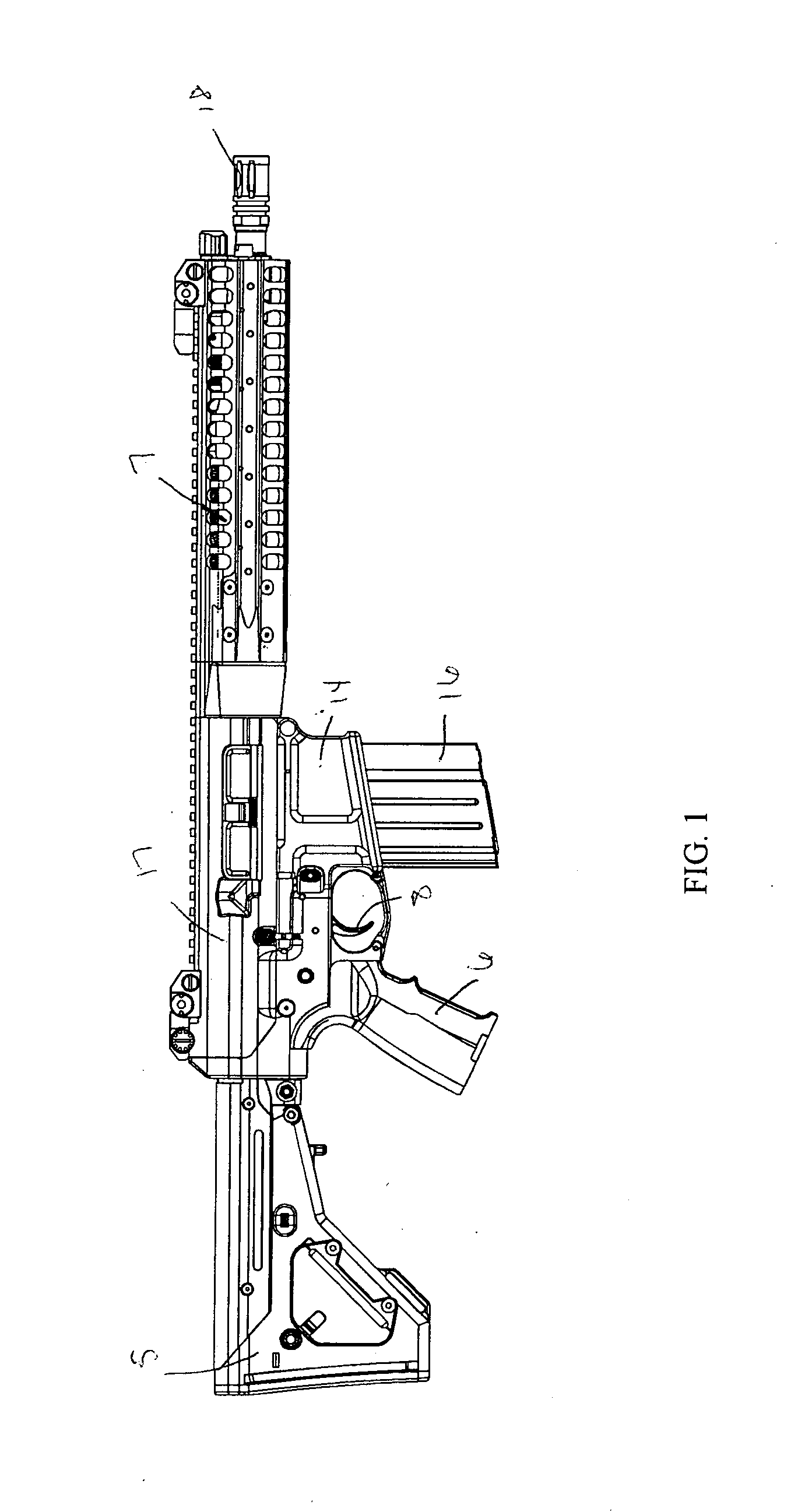
[0035]The present invention utilizes a number of physical principles to enhance the motion of parts in a firearm. The manner in which the present invention utilizes these principles to provide a modular ambidextrously operated firearm will be shown and described in greater detail with reference to FIGS. 1 through 7.

[0036]For this application, the phrases “connected to,”“co...


PUM


Abstract

An ambidextrously operated bolt catch assembly for a firearm facilitates ease of use by either right handed or left handed shooters. The ambidextrous bolt catch assembly includes two levers, one on each side of the firearm, that interact with each other. Each lever has a primary contact surface and a secondary contact surface. By depressing the primary contact surface of either lever, both levers rotate to move the bolt catch assembly from a displaced position to a static position. Conversely, by depressing the secondary contact surface of either lever, both levers rotate to move the bolt catch assembly from a static position to a displaced position.

Description

BACKGROUND OF THE INVENTION[0001]1. Field of the Invention[0002]The present invention relates generally to firearms and more particularly to firearm receivers with ambidextrous controls.[0003]2. Description of the Related Art[0004]In modern warfare individual infantry men still play a significant role in military operations. An individual soldier's effectiveness depends, to a large extent, on the speed at which the individual solider can manipulate the controls of the issued firearm. As such, ergonomic and ambidextrously designed controls can be critical. Various situations arise which require an infantry man to operate the bolt catch of a firearm.[0005]A soldier's ability to provide a high rate of accurate fire on target is critical on the modern battle field. Detachable box magazines are the most common ammunition feeding device used with modern firearm designs. Examples of this are found in the M16 series of firearms, German G3 and the Belgian FAL. Designs such as the M16 and FAL...

Claims


Application Information

Patent Timeline
IPC IPC(8): F41A3/12
CPCF41A35/06F41A17/42
Inventor GOMEZ, JESUS S.
Owner LWRC INTERNATIONAL
Learn More