Eureka AIR delivers breakthrough ideas for toughest innovation challenges, trusted by R&D personnel around the world.

Power swing arm mechanism of cutting machine and cutting machine

A cutting machine and power technology, which is applied in the field of power swing arm mechanism and cutting machine, can solve the problems of motor and electrical components damage, escape, and difficulty in dynamic sealing.

Pending Publication Date: 2021-06-04
上海刃安实业有限公司
View PDF6 Cites 1 Cited by
  • Summary
  • Abstract
  • Description
  • Claims
  • Application Information

AI Technical Summary

Problems solved by technology

This design can transfer the motor from the wet cabin with high humidity to the dry cabin, which improves the reliability of the motor, but the problem is that the deflection track of the power end is a circular arc, so the dry and wet separation plate should be left in a circular arc shape. Hole, the dynamic sealing of the hole is difficult, there will always be corrosive water mist escaping into the dry compartment, and in the long run, causing damage to the motor and electrical components

Method used


Image

  • Power swing arm mechanism of cutting machine and cutting machine

Examples


Embodiment 1

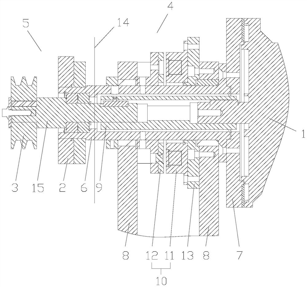
[0020] see figure 1 , the present invention provides a power swing arm mechanism of a cutting machine, which is arranged on a cutting machine with a dry cabin 4 and a wet cabin 5 .

[0021] The power swing arm mechanism of the cutting machine comprises a motor 1, a handle, a swing arm 2, a driving wheel 3, a driven wheel and a transmission belt.

[0022] The motor 1 is arranged in the dry chamber 4 and is rotatably connected to the cutting machine. The rotating shaft of the motor 1 extends to the wet chamber 5 . The swing arm 2 is fixedly connected with the motor 1 . The driving wheel 3 is coaxially fixed with the rotating shaft, and the driven wheel is rotatably arranged on the swing arm 2 for fixing the cutting blade, and the driven wheel and the driving wheel 3 are connected by a transmission belt. The handle is fixed on the motor 1 for driving the motor 1 to rotate.

[0023] Motor 1 is arranged in the dry cabin 4, has prevented the water vapor erosion in the wet cabin ...

Embodiment 2

[0029] see figure 1 , a cutting machine, including the power swing arm mechanism of the cutting machine as described in Embodiment 1, and also includes a dry cabin 4 and a wet cabin 5. The dry compartment 4 and the wet compartment 5 are separated by a partition 14, and a through hole is provided on the partition 14, and a sealing ring is provided on the through hole.

[0030] One end of the sleeve flange 6 is fixedly connected with the motor 1 in the dry compartment 4, and the other end is fixedly connected with the driving wheel 3 through the through hole on the partition plate 14, and the outer wall of the sleeve flange 6 is sealed with the through hole. Ring interference fit, so that there is no gap between the dry cabin 4 and the wet cabin 5, further preventing the possibility of fog entering the dry cabin 4.

[0031] In summary, the present invention can greatly reduce the sealing difficulty of the wet and dry cabin 5, and prevent the wet cabin 5 from eroding water mist ...


PUM


Abstract

The invention provides a power swing arm mechanism of a cutting machine and the cutting machine, and relates to the technical field of cutting machines. The power swing arm mechanism of the cutting machine comprises a motor, a handle, a swing arm, a driving wheel, a driven wheel and a transmission belt. The motor is arranged in the dry cabin; a rotating shaft of the motor provides power for rotation of the cutting blade through the driving wheel, the driven wheel and the transmission belt; the motor is rotationally connected with the cutting machine, the motor can be pushed to rotate through the handle fixed to the motor, the swing arm fixed to the motor is driven to rotate, the set angle of the swing arm is changed, meanwhile, the driven wheel is rotationally arranged on the swing arm, and when the angle of the swing arm is changed, the position of the driven wheel is directly driven to change; the position of the cutting blade fixed on the driven wheel is changed, the cutting function of the cutting machine is achieved, meanwhile, the problem of dynamic sealing of holes in the prior art is avoided, the blocking effect on corrosive water mist is achieved, and the overall service life of the cutting machine is greatly prolonged.

Description

technical field [0001] The invention relates to the technical field of cutting machines, in particular to a power swing arm mechanism of the cutting machine and the cutting machine. Background technique [0002] The cutting of metallographic samples is grinding of cutting discs, and the temperature of the slit is high. In order to ensure the original metallographic structure of the sample, cooling liquid is usually used to cool down. The introduction of cooling liquid will put forward higher requirements for the corrosion resistance of the equipment. [0003] Generally speaking, metallographic cutting machines are divided into dry and wet positions. The wet cabin is used to spray coolant and perform cutting tasks; the dry cabin is used to install electronic control components. The cutting motor is the main power source, the power is relatively large and the volume is relatively large. The installation position of the motor determines the technical direction of the cutting m...

Claims


Application Information

Patent Timeline
Patent Type & Authority Applications(China)
IPC IPC(8): G01N1/04B23D19/08
CPCG01N1/04B23D19/08
Inventor 肖爽怀
Owner 上海刃安实业有限公司
Why Eureka
Eureka Blog
Learn More