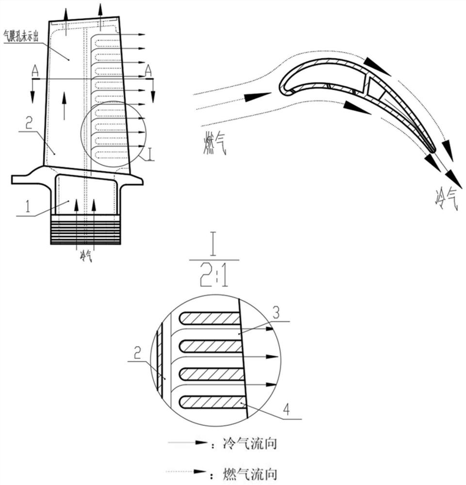
Turbine blade adopting chordwise rotary cooling channel
A technology for turbine blades and cooling passages, applied in the direction of blade support elements, machines/engines, mechanical equipment, etc., can solve the problems of short flow distance, low cooling effect, small heat transfer area of cold air and trailing edge, etc., to increase The ability to heat, improve the cooling effect, and avoid the effect of excessive temperature rise
- Summary
- Abstract
- Description
- Claims
- Application Information
AI Technical Summary
Problems solved by technology
Method used
Image
Examples
Embodiment 1
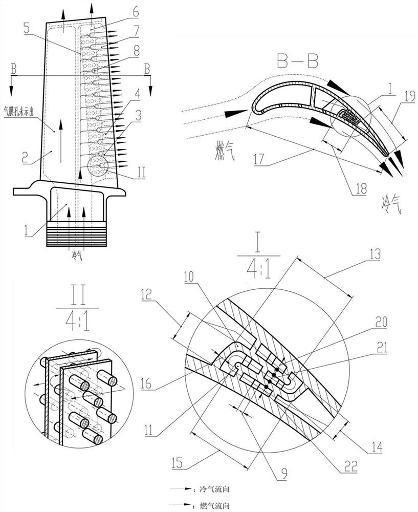
[0027] A turbine blade using a chord-direction rotary cooling channel is mainly composed of a gas collection cavity 5, a rotary cavity 6, and an exhaust cavity 7, such as figure 2 shown.
[0028] The hollow turbine blade 1 with a chord length L=40 mm is provided with an inner cavity cold air passage 2 for low-temperature cooling gas to flow inside the blade to cool the blade. The air collection chamber 5 guides the cold air from the blade root into the interior of the blade, flows downstream into the swivel chamber 6, and the length of the swirl chamber is L 1 = 6mm. The cold air makes two 180° turns in the cavity along the chord direction from the blade back to the blade pot. The cavity is composed of an L-shaped partition wall 10 on the side of the basin, an L-shaped partition wall 11 on the back side, and circular spoiler columns 8 staggeredly combined. The short side of the basin side L-shaped partition wall 10 is vertically connected with the leaf basin, and its lengt...
Embodiment 2
[0030] A turbine blade using a chord-direction rotary cooling channel is mainly composed of a gas collection cavity 5, a rotary cavity 6, and an exhaust cavity 7, such as Figure 4 shown
[0031] The hollow turbine blade 1 with a chord length L=40 mm is provided with an inner cavity cold air passage 2 for low-temperature cooling gas to flow inside the blade to cool the blade. The air collection chamber 5 guides the cold air from the root of the blade into the interior of the blade, flows downstream and enters the rotary chamber, and its length is L 1 = 6 mm. The cold air makes two 180° turns along the chord direction from the blade pot to the blade back in the cavity. The cavity is composed of an L-shaped partition wall 10 on the side of the basin, an L-shaped partition wall 11 on the back side, and circular spoiler columns 8 staggeredly combined. The short side of the basin side L-shaped partition wall 10 is vertically connected with the leaf basin, and its length l 1 = 2...
Embodiment 3
[0033] As shown in Fig. 5(a), a turbine blade with chordwise rotating cooling channels is used on both the leading edge and the trailing edge. The structure of the leading edge of the blade is similar to that of the trailing edge, and is also composed of an air collecting chamber 5, a rotary chamber 6 and an exhaust chamber 7. The front exhaust cavity is composed of an L-shaped partition wall 23 on the side of the front edge basin, an L-shaped partition wall 24 on the back side of the front edge, and circular spoiler columns 8 staggeredly combined. The short side of the L-shaped partition wall 23 on the side of the front edge basin is vertically connected to the leaf basin, and the short side of the L-shaped partition wall 24 on the back side of the front edge is vertically connected to the leaf back. The cold air makes two 180° turns along the chord direction from the back of the blade to the blade pot in the leading edge and then is discharged from the air film hole on the l...
PUM
 Abstract
Description
Claims
Application Information
 - R&D
- Intellectual Property
- Life Sciences
- Materials
- Tech Scout
- Unparalleled Data Quality
- Higher Quality Content
- 60% Fewer Hallucinations
Browse by: Latest US Patents, China's latest patents, Technical Efficacy Thesaurus, Application Domain, Technology Topic, Popular Technical Reports.
© 2025 PatSnap. All rights reserved.Legal|Privacy policy|Modern Slavery Act Transparency Statement|Sitemap|About US| Contact US: help@patsnap.com


