
Turbine blade adopting buckle fixing type ceramic armor

A turbine blade, fixed technology, applied in the direction of blade support components, engine components, machines/engines, etc., can solve the problems of low cooling effect and large cooling air consumption

Active Publication Date: 2021-06-04
DALIAN UNIV OF TECH
View PDF5 Cites 1 Cited by
  • Summary
  • Abstract
  • Description
  • Claims
  • Application Information

AI Technical Summary

Problems solved by technology

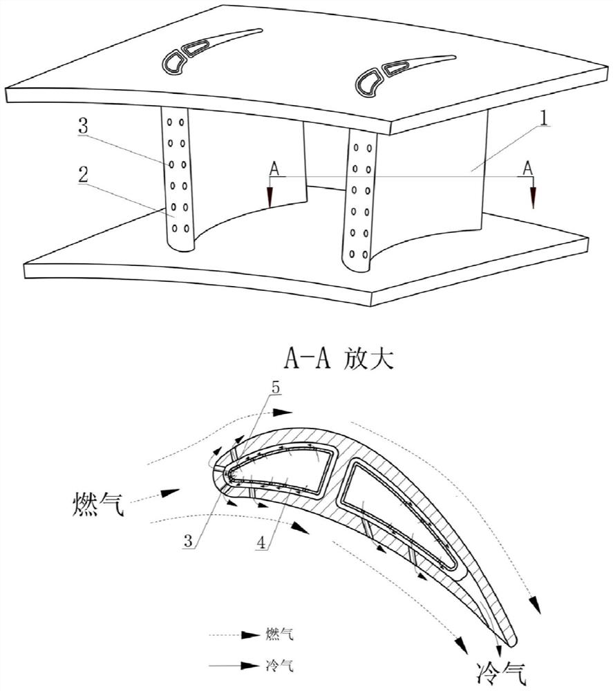
However, with the further increase of the turbine intake temperature of the next-generation engine, this type of structure has exposed the shortcomings of low cooling effect and large cooling air consumption, which can no longer meet the requirements. There is an urgent need to improve the blade cooling structure and reduce the cooling air consumption.

Method used


Image

  • Turbine blade adopting buckle fixing type ceramic armor
  • Turbine blade adopting buckle fixing type ceramic armor
  • Turbine blade adopting buckle fixing type ceramic armor

Examples


Embodiment 1

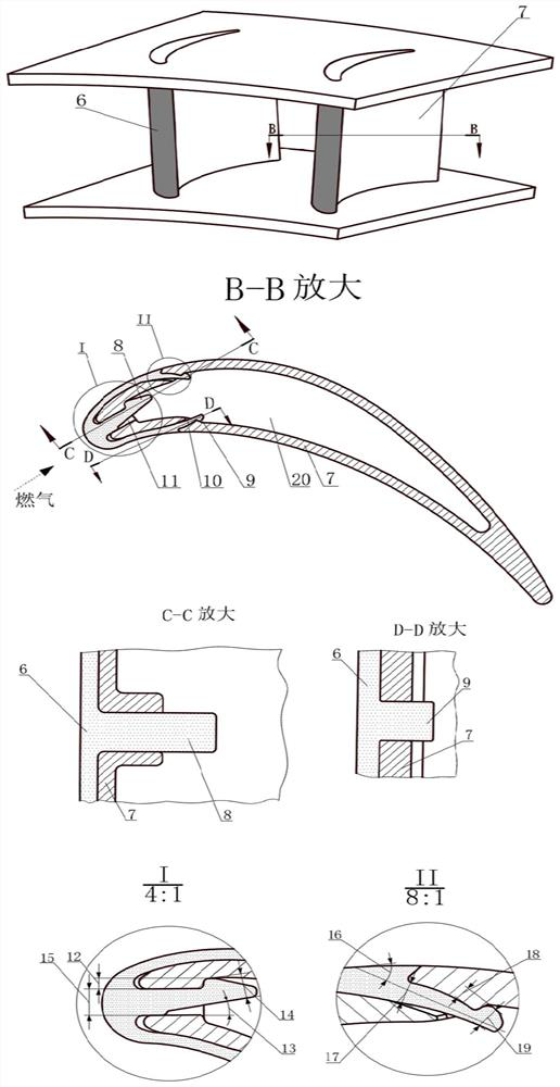
[0024] see figure 2 , the present embodiment provides a turbine blade using a leading edge fixing buckle 8 facing the blade back and an outer buckle-type blade body fixing buckle 9 . Its structure includes a leading edge 6 of ceramic matrix composite material and a metal matrix 7 . It is connected through the fixing buckle on the leading edge 6 of the ceramic matrix composite material and the corresponding fixing groove on the metal base 7 . In detail, the heads of the leading edge fixing buckle 8 and the blade body fixing buckle 9 are both facing the back of the blade, and the direction of the leading edge fixing buckle 8 is parallel to the incoming gas. The typical dimensions of this embodiment are: front edge fixed buckle boss width W 1 =0.5mm; front edge fixed buckle head inclination angle ∠θ 1 =15°; Width of front edge fixed buckle head W 2 =1.4mm; front edge fixed buckle width W 3 = 1.4 mm. The angle between the leaf body fixing buckle and the outer wall surface ∠...

Embodiment 2

[0026] see Figure 4 and Figure 5, the present embodiment provides a turbine blade with a leading edge fixing buckle 8 facing the blade pot and an inner buckle blade airfoil fixing buckle 9 . In this example, the direction of the leading edge fixing buckle 8 is parallel to the incoming gas flow, and the head of it and the inner buckle airfoil fixing buckle 9 both face the side of the blade pot. And fix the buckle boss width W towards the front edge of the leaf pot 7 The typical value range of 21 is W 7 = 0.3 mm ~ 1 mm. The typical dimensions of this implementation case are: the width W of the fixed buckle boss towards the front edge of the blade pot 7 =0.4mm; front edge fixed buckle head inclination angle ∠θ 1 =16°; Width of front edge fixed buckle head W 2 =1.2mm; front edge fixed buckle width W 3 = 1.2 mm.

[0027] Inner buckle blade body fixing buckle installation angle ∠θ 3 The typical value range of 22 is 12°~45°; 8 The typical value range of 23 is 0.3mm~1mm....


PUM


Abstract

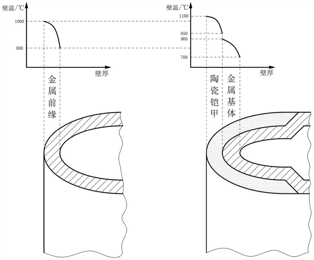
The invention belongs to the technical field of turbine blades of aero-engines, and relates to a turbine blade adopting a buckle fixing type ceramic armor. The invention discloses the turbine blade adopting the buckle fixing type ceramic armor. According to the structural scheme of the turbine blade, for the front edge area of the turbine blade, a ceramic matrix composite component and a blade metal matrix can be rapidly and stably connected, in addition, on the premise that the original pneumatic shape of the blade is not damaged, the front edge area of the turbine blade is effectively protected, use of cooling gas is reduced, so that the high-temperature resistance of the blade is improved, and the thrust performance of the engine is improved; and meanwhile, after the ceramic armor is damaged, the ceramic armor can be conveniently replaced in the maintenance process, in addition, the high-value blade metal matrix can be recycled, the service life is prolonged, and therefore the use and maintenance economical efficiency of the engine is greatly improved.

Description

technical field [0001] The invention belongs to the technical field of turbine blades of aero-engines, and relates to a turbine blade adopting buckle-fixed ceramic armor. Background technique [0002] For an aero turbine engine, an increase in the gas temperature before the turbine means an increase in engine thrust and performance. On the basis of the existing 1500°C level, if the turbine intake temperature increases by 100°C, the thrust of the engine can be increased by more than 10%. According to predictions, the temperature before the turbine of advanced aero-engines in the future may exceed 1800°C, which is much higher than the safe working temperature of known superalloys and the cooling capacity of conventional cooling measures. For this reason, solving the problem of insufficient temperature bearing capacity of turbine blades is the key to the development of high thrust-to-weight ratio aeroengines. For the turbine guide vanes, the leading edge part directly bears t...

Claims


Application Information

Patent Timeline
Patent Type & Authority Applications(China)
IPC IPC(8): F01D5/14F01D5/18F01D5/28
CPCF01D5/141F01D5/147F01D5/18F01D5/282F01D5/284
Inventor 吕东孙智强蔚夺魁吴伟龙王楠孙一楠
Owner DALIAN UNIV OF TECH
Learn More