
Collet type cutter structure

A tool and collet technology, which is applied in the field of collet tool structure, can solve the problems that the tool spindle 7 cannot be used to automatically load and retract the tool, does not have the function of changing the tool, and manually loads the tool, etc.

Active Publication Date: 2021-06-04
YAMAKEN TOOL
View PDF7 Cites 0 Cited by
  • Summary
  • Abstract
  • Description
  • Claims
  • Application Information

AI Technical Summary

Problems solved by technology

[0005] and for example As shown in Figure 11, it is the first collet cutter 9a, and the first collet cutter 9a is set to be equipped with a first collet 10 at the front end of a knife handle 92a , and then use a nut cover 93 to press the collet 10 to clamp an end mill or drill bit, that is, the cutter bar 91, but the first collet cutter 9a cannot be used for the automatic upper tool of the above-mentioned tool spindle 7 And retract the tool, so that the first type of collet tool 9a can not be used in the automatic tool change of the ATC tool magazine of the CNC machine tool, and the tool must be changed manually, which affects the working efficiency of the processing machine
[0006] There is also a second type of collet type cutter 9b that does not use the nut cover 93, and cooperates with such as Figure 12, the second type of collet cutter 9b uses a screw 94 and a pad block 95 to tighten the second collet 10b and combine it with its handle 92, the collet is a heat-shrinkable collet, and the second collet 10b and a knife bar 91 must be locked manually, so that the The second type of collet tool 9b cannot be applied to the automatic loading and unloading of the tool spindle 7, that is, the second type of collet tool 9b cannot be applied to the automatic tool change of the ATC tool magazine of the CNC machine tool
To sum up, due to the influence of its structure, the existing collet-type cutting tools can only be loaded and retracted manually, and do not have the tool changing function to cooperate with CNC processing machines to automatically load and retract the tool.

Method used


Image

  • Collet type cutter structure
  • Collet type cutter structure
  • Collet type cutter structure

Examples


Embodiment Construction

[0042] The principles and features of the present invention are described below in conjunction with examples, which are only used to explain the present invention and are not intended to limit the scope of the present invention.

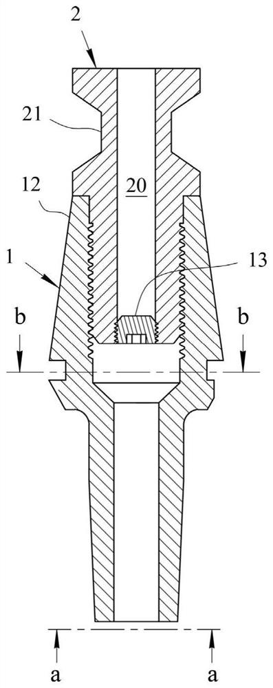
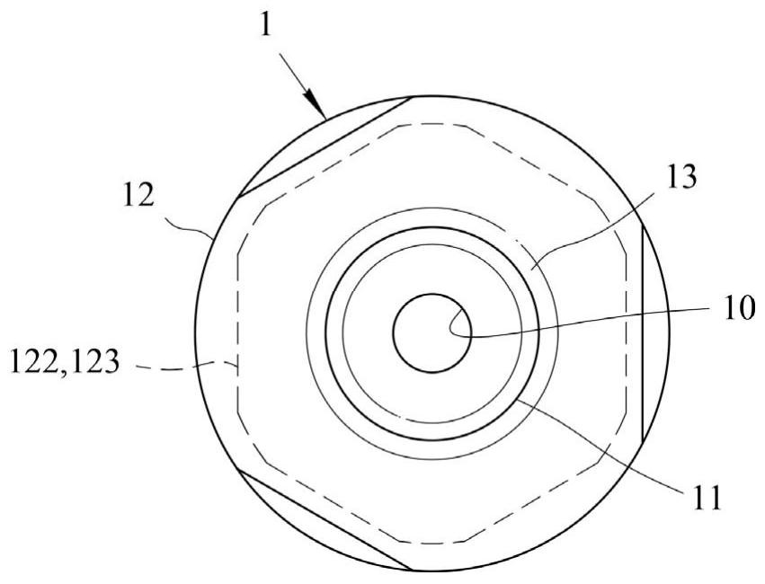
[0043] Such as Figure 1-Figure 7 As shown, a collet-type tool structure includes a stepped rod 1 and a buckle rod 2. The stepped rod 1 includes a first rod body 11 and a second rod body 12. The first channel 10, the second rod body is provided with a tapered structure suitable for the inner taper hole of the tool spindle, the second rod body is provided with a threaded hole, and the upper part of the buckle rod 2 is provided with a There is a fastening groove 21 matched with the inner retracting claw, and the fastening rod is provided with an external thread matching the threaded hole.

[0044] A hollow second channel 20 for supplying cooling liquid is provided in the fastening rod. Coolant can enter the tool structure through the second channel for...


PUM


Abstract

The invention discloses a collet chuck type cutter structure which comprises a step rod and a buckling rod, the step rod comprises a first rod body and a second rod body, the first rod body is provided with a first channel used for installing a cutter rod, the second rod body is provided with a conical structure matched with an inner conical hole of a cutter main shaft, a threaded hole is formed in the second rod body, and the buckling rod is connected with the threaded hole. The upper portion of the buckling rod is provided with a buckling groove matched with a tool retracting buckling claw in a tool spindle, and the buckling rod is provided with an external thread matched with the threaded hole. And a second channel is arranged in the buckling rod. And a water stop screw is arranged on the buckling rod and is arranged at the lower end of the second channel. And a groove part convenient for a wrench tool to operate is arranged on the step rod. The collet chuck type tool is simple in structure and convenient to operate, and can be matched with an ATC tool magazine of a CNC machine tool to achieve the purposes of metal cutting machining and automatic tool changing without using a tool handle, so that the working efficiency of metal machining is improved.

Description

technical field [0001] The invention relates to a collet-type cutter structure, which belongs to the technical field of cutter clamping. Background technique [0002] The full name of CNC is Computer Numeric Control, which is computer numerical control, and CNC machining center (MACHINE CENTER), which is a CNC machine tool controlled by computer numerical control; The instructions of the program cut the required material workpiece into the required shape. [0003] Usually, the CNC machining center machine system will be provided with an ATC tool magazine (Automatic Tool Changer, ATC for short) next to its tool spindle, as disclosed by the name of the announcement number TWM481784U, which is a tool changer for CNC center processing machines, wherein the tool The warehouse will be equipped with various face milling cutters, end milling cutters, large and small drills, etc. In addition, an automatic tool changer 8 will be provided between the tool magazine and the tool spindle...

Claims


Application Information

Patent Timeline
IPC IPC(8): B23Q3/12B23C5/26
CPCB23Q3/12B23C5/26
Inventor 何明康
Owner YAMAKEN TOOL
Learn More