Battery structure capable of injecting liquid from bottom and battery liquid injection method

A battery and liquid injection technology, applied in structural parts, battery pack parts, circuits, etc., can solve problems such as electrolyte waste, corrosion of liquid injection devices, and inability to ensure full infiltration of internal cells, so as to improve fluency and ensure wetting effect

Pending Publication Date: 2021-06-01
GUIZHOU ZHONG RUI FENG TAI NEW ENERGY TECH CO LTD
View PDF14 Cites 2 Cited by
  • Summary
  • Abstract
  • Description
  • Claims
  • Application Information

AI Technical Summary

Problems solved by technology

[0004] The research and development personnel of the technical solution of the present invention analyzed the previous similar battery liquid injection technology and found that the previous battery liquid injection technology was affected by factors such as its liquid injection method, liquid injection position, battery itself structure, sealing means, and cell infiltration degree. Influence, but can not achieve the ideal injection effect, the specific analysis is as follows:
[0005] First, take lithium batteries as an example, which are widely used in mobile phones, notebook computers, digital cameras, electric vehicles, electric tools, and new energy vehicles. At present, most manufacturers inject electrolyte into batteries by Holes are opened on the upper surface of the battery to inject liquid downward, which is completed through the following processes: vacuuming, quantitative liquid injection, pressurization, and battery discharge. This liquid injection method is a sleeve-type liquid injection method, and quantitative liquid injection is used. , the amount of liquid injected each time is the same, and then the more times of liquid injection, because the liquid is injected directly from the upper liquid injection hole, not only cannot ensure that the internal cells are fully infiltrated, but also cause waste of electrolyte, which will increase the production cost , in addition, if an accident occurs, it will also cause certain corrosion to the liquid injection device
[0006] Second, for many metal-packaged battery structures, molybdenum rods and steel rings are usually arranged on the upper surface. The molybdenum rods have a high melting point, good thermal conductivity and low thermal expansion, and are often used to manufacture electrodes. If Adding a liquid injection hole around the molybdenum rod or steel ring or the sealing structure configured on the upper surface, obviously, this will not only affect the smoothness of battery liquid injection, but also cause certain damage to the stability of the battery's own structure, making it difficult to ensure the stability of the battery. Service life and application performance, which is also a common disadvantage of adding liquid injection holes from the upper surface
[0007] Third, it is known from the above analysis that if the liquid injection method of taking out the battery cell and putting it into the electrolyte and then letting the electrolyte penetrate into the battery is also a common liquid injection method in this field, but this method belongs to The method of taking out the battery and operating it alone obviously has obvious disadvantages in terms of liquid injection efficiency, labor cost, and ensuring the rigorousness of the battery structure, which is not conducive to the continuity and smoothness of the battery liquid injection operation.
[0008] Therefore, for the technical means currently used for battery liquid injection, it is neither suitable for the liquid injection method of taking out the battery cell alone, nor is it suitable for the liquid injection method of configuring the liquid injection hole on the upper surface to inject liquid downward.

Method used


Image

  • Battery structure capable of injecting liquid from bottom and battery liquid injection method
  • Battery structure capable of injecting liquid from bottom and battery liquid injection method
  • Battery structure capable of injecting liquid from bottom and battery liquid injection method

Examples


Embodiment 1

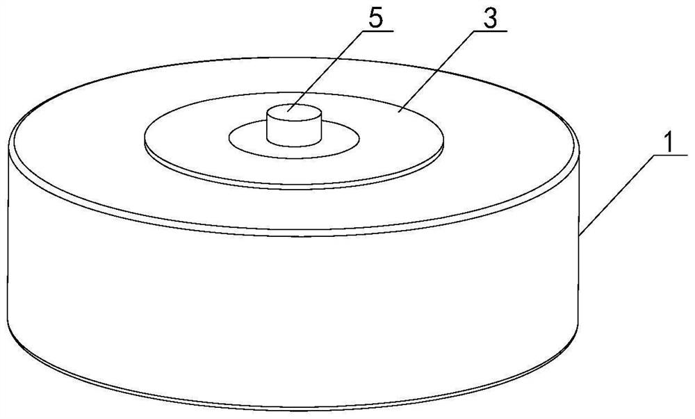
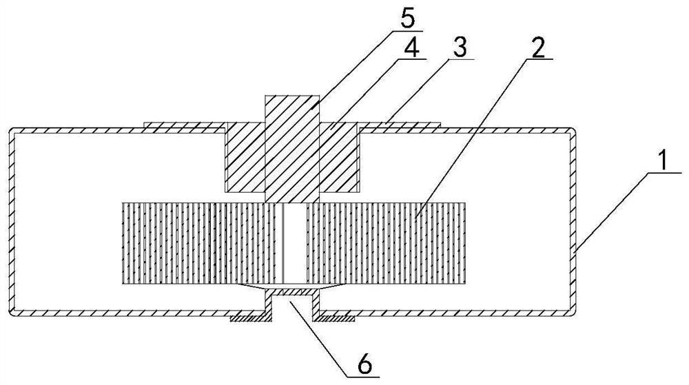
[0052] Such as figure 1 , figure 2 , image 3 , Image 6 As shown, the battery structure with liquid injection from the bottom implemented by the technical solution of the present invention includes a battery case 1 with a cylindrical structure, and its interior is set as a hollow structure, so as to be used for assembling the battery cell 2 and containing the injected electrolyte , a molybdenum rod pole 5 is arranged at the center of the battery cell 2. Since an opening is provided on the top of the battery case 1, the molybdenum rod pole 5 can pass through the battery case 1 from bottom to top and extend to the battery case 1. The outside, wherein the opening is also used to install the ring-shaped steel ring 3 that can seal and fix the assembled battery cell 2 to a certain extent. The gap between the pole 5 and the steel ring 3 is filled with an annular glass layer 4. The structure implemented above forms the basic part of the battery structure. It is based on this basi...

Embodiment 2

[0056] Such as Figure 4-5 As shown, the battery structure of injecting liquid from the bottom implemented in Embodiment 2 of the present invention is the supplement and improvement of the technical means implemented in Embodiment 1. On the premise of improving the fluency of the battery liquid injection operation, technicians Corresponding technical means can also be further implemented to form corresponding technical solutions, specifically including:

[0057] A ring-shaped support assembly 7 is horizontally added to the bottom surface of the inner chamber of the battery case 1 around the periphery of the implemented liquid injection hole position 6. Of course, for the specific material of the support assembly 7, an assembly that has no effect on the performance of the battery cell 2 can be selected, and further , two layers of diversion supports are set above the implemented support assembly 7, and from the inside to the outside are diversion supports one 8 and diversion su...

Embodiment 3

[0062] Such as Figure 1-4 As shown, Embodiment 3 of the present invention implements a battery liquid injection method, which is a supplement and improvement to the technical means implemented in Embodiment 1 or Embodiment 2. On the premise that it is beneficial to improve the fluency of battery liquid injection operation, Technicians can further implement corresponding technical means according to the battery structure to form corresponding method steps, specifically including:

[0063] (1) Select the battery to be injected with electrolyte, open a liquid injection hole 6 at the center of the bottom surface of the shell, and align the middle space area 10 of the battery 2 when assembling the battery 2 into the battery. The liquid injection hole 6, so that the liquid injection hole 6 is kept in communication with the middle space area 10;

[0064] (2) Inject the electrolyte solution from the set liquid injection hole 6 from the bottom up to the inside of the battery, so that...


PUM


Abstract

The invention relates to a battery structure capable of injecting liquid from bottom. A battery cell of the battery structure is horizontally arranged on the bottom surface of a battery shell or a bottom surface support of the battery shell, and a middle space region of the battery cell is aligned to the central position of the bottom surface of the battery shell; and a liquid injection hole position of the battery is formed in the center position of the bottom surface of a battery shell, and electrolyte is injected into an inner cavity of the battery shell from bottom to top through the liquid injection hole position, so that the electrolyte is directly dispersed and guided to each region of the surface of the battery cell from the liquid injection hole position through a middle space region of the battery cell. According to the battery structure provided by the invention, the liquid injection hole is formed in the bottom part of the battery for liquid injection, and the space at the central position of the internal battery cell is ingeniously utilized and matched with the corresponding flow guide structure, so that the smoothness of liquid injection operation of the battery can be improved on the premise of not influencing the stability of the structure of the battery, and the full infiltration of the battery cell can be ensured.

Description

technical field [0001] The invention relates to the technical field of batteries, in particular to a battery structure and a battery liquid injection method for liquid injection from the bottom. Background technique [0002] For battery liquid injection technology, it is generally based on controlling the amount of liquid electrolyte and the injection time, so that the liquid electrolyte is injected into the battery from the liquid injection port. The lithium ions in the battery can migrate between the positive and negative plates to achieve a reversible cycle. From the perspective of conventional technical means, the liquid injection process is mainly affected by two factors: the liquid injection system and the system pressure, and the system pressure will affect the battery liquid injection. Preparation, liquid injection, pre-sealing infiltration and post-sealing infiltration and other processes are affected, and it is also the most important factor affecting the process o...

Claims


Application Information

Patent Timeline
Patent Type & Authority Applications(China)
IPC IPC(8): H01M50/627
CPCY02E60/10H01M50/627
Inventor 陈海峰
Owner GUIZHOU ZHONG RUI FENG TAI NEW ENERGY TECH CO LTD
Why Eureka
Try Eureka