Method for improving gas circulation uniformity of vertical tubular furnace

A tube furnace, uniformity technology, applied in the direction of furnace, crucible furnace, furnace type, etc., can solve the problems of difficult gas passage, gas blockage, unstable crucible placement, etc., and achieve the effect of improving accuracy and uniformity

Pending Publication Date: 2021-11-02
XI'AN UNIVERSITY OF ARCHITECTURE AND TECHNOLOGY
View PDF6 Cites 0 Cited by
  • Summary
  • Abstract
  • Description
  • Claims
  • Application Information

AI Technical Summary

Problems solved by technology

However, some furnace tubes only have a round hole-shaped channel in the middle of the plug, or even no channel. When the crucible is placed on the plug, the crucible will cover the channel hole, making it difficult for gas to pass through, which seriously affects the gas circulation in the furnace tube. uniformity, and even cause gas blockage, making it difficult to pass through normally
For this reason, some experimenters built a bracket on the plug to leave a gas channel, but this caused the crucible to be placed unstable or even toppled over, which caused great difficulties.

Method used


Image

  • Method for improving gas circulation uniformity of vertical tubular furnace
  • Method for improving gas circulation uniformity of vertical tubular furnace
  • Method for improving gas circulation uniformity of vertical tubular furnace

Examples


Embodiment 1

[0024] Example 1: Method for improving the uniformity of vertical tubular furnace gas.

[0025] (1) First, the central position of the solid cylindrical plug in the diameter of 200 mm is opened to a hole in diameter of 10 mm, so that it runs through the entire plug;

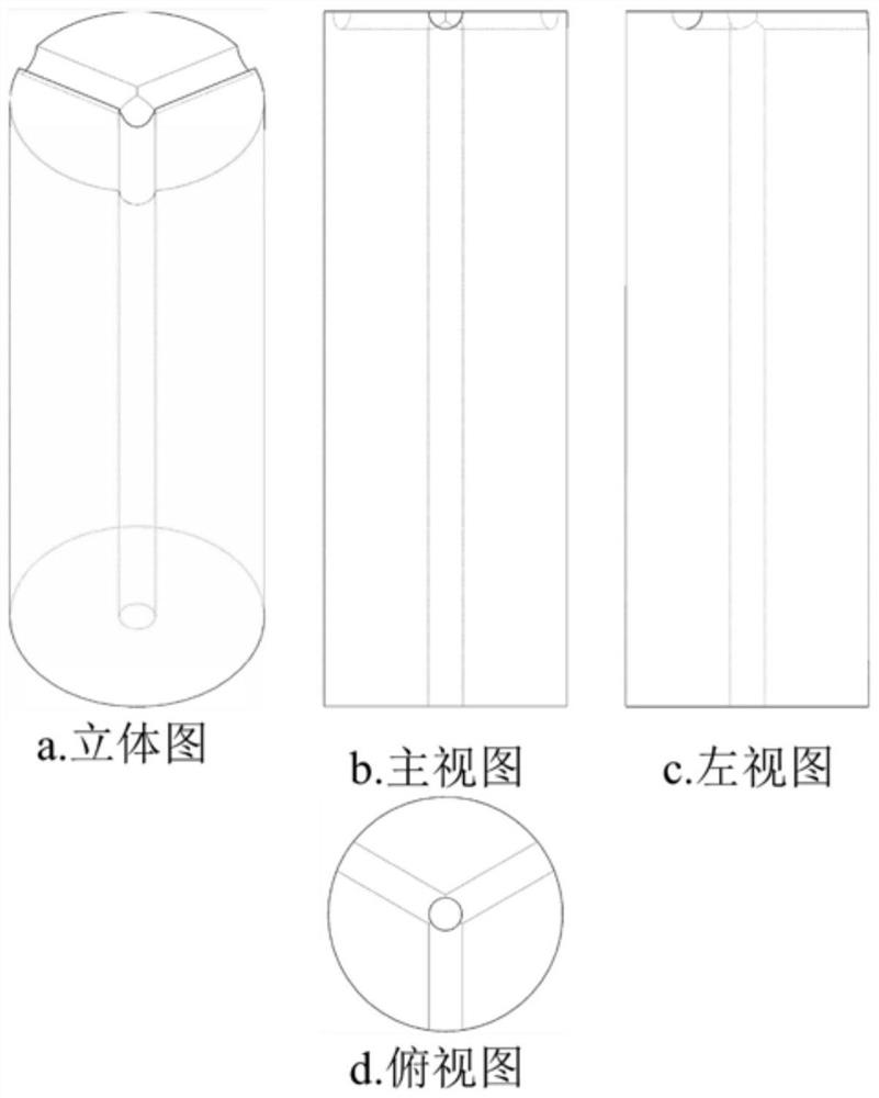
[0026] (2) Place the plug of the penetrating holes in step (1), at the top, from the circumferential direction, 3 towards a uniform semicircular passage of 3 mm distribution in the radial center in the radial direction. Schematic figure 1 Indicated. When the gas flows upward from the plug, reaching the top of the crucible is dispersed to three passages to be diffused above, and the gas flow uniformity conditions are improved.

Embodiment 2

[0027] Example 2: A method of improving the uniformity of vertical tubular furnace gas.

[0028] (1) First, the central position of the solid cylindrical plug in the diameter of 200 mm is opened to a hole in diameter of 10 mm, so that it runs through the entire plug;

[0029] (2) Place the plug of the penetrating holes in step (1), at the top, from the circumference, toward the center of 4 having a uniform diameter of 10 mm to the center in the radial direction. Schematic figure 2 Indicated. When the gas flows upward from the plug, reaching the top of the crucible is dispersed to four passages to diffuse overward, and the gas flow uniformity conditions are improved.

Embodiment 3

[0030] Example 3: A method of improving the uniformity of vertical tubular furnace gas.

[0031] (1) First, the central position of the solid cylindrical plug in the diameter of 200 mm is opened to a hole in diameter of 10 mm, so that it runs through the entire plug;

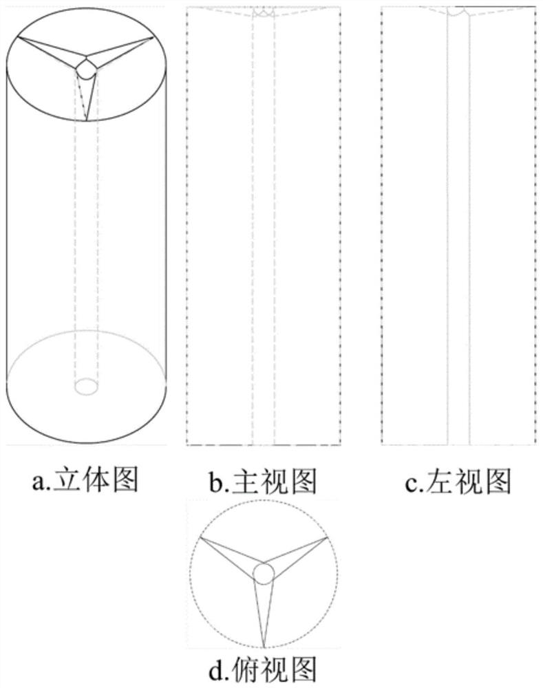
[0032] (2) Place the plug of the penetrating hole in the step (1), and 35 mm of 35 mm, a height of 35 mm, a height of 35 mm, and a uniform distribution. Schematic image 3 Indicated. When the gas flows upward from the plug, reaching the top of the crucible is dispersed to three passages to be diffused above, and the gas flow uniformity conditions are improved.


PUM


Abstract

The invention discloses a method for improving gas circulation uniformity of a vertical tubular furnace.The method comprises the steps of: (1) punching a hole with the diameter of 5-10 mm in the circle center position of a solid cylindrical plug, and enabling the hole to penetrate through the whole plug; and (2) vertically placing the plug punched with the through holes in the step (1), and punching 3-4 uniformly-distributed channels with the diameters of 5-10mm from the circumference to the circle center along the radius direction at the top. The method can obviously improve the uniformity of circulating gas. The plug is modified, so that the circulation path of the circulating gas is adjusted, the uniformity of the circulating gas is improved, and then the accuracy in an experiment process is improved.

Description

Technical field [0001] The present invention belongs to the technical field of vertical tube furnaces, and in particular, a method of improving the uniformity of vertical tubular furnace gas. Background technique [0002] Commonly used vertical tubular furnaces are made of light refractory materials, and on the one hand, it is supported and on the other hand. During use, the crucible is placed above the plug to heat, and the metallurgical experiments often need to pass a certain flow of gas in the cooker. However, a partial furnace tube only has a circular hole passage in the middle of the plug, and even there is no passage. When the crucible is placed on the plug, the crucible will cover the channel holes, the gas is difficult to pass, which seriously affects the gas flow in the cooker. Uniformity, even cause gas blockage, it is difficult to pass. For this part of the experimenter builds a bracket on a plug to leave a gas passage, but causes a case where the 坩 坩 is placed instab...

Claims


Application Information

Patent Timeline
Patent Type & Authority Applications(China)
IPC IPC(8): F27B14/08F27D7/00
CPCF27B14/08F27D7/00
Inventor 崔雅茹王国华李小杰李小明杨泽李倩
Owner XI'AN UNIVERSITY OF ARCHITECTURE AND TECHNOLOGY
Why Eureka
Try Eureka