
Anti-drift valve devices, blade devices and working machinery

An anti-drift, valve device technology, used in mechanical equipment, accumulator devices, earth movers/shovels, etc., can solve problems such as difficulty in obtaining proper operation of pistons

Active Publication Date: 2022-03-04
CATEPILLAR SARL
View PDF8 Cites 0 Cited by
  • Summary
  • Abstract
  • Description
  • Claims
  • Application Information

AI Technical Summary

Problems solved by technology

In this configuration, when the piston of the pilot check valve pushes the poppet valve in the valve opening direction, head side pressure and rod side pressure will be applied to the piston, and it is difficult to obtain proper operation of the piston

Method used


Image

  • Anti-drift valve devices, blade devices and working machinery
  • Anti-drift valve devices, blade devices and working machinery
  • Anti-drift valve devices, blade devices and working machinery

Examples


Embodiment Construction

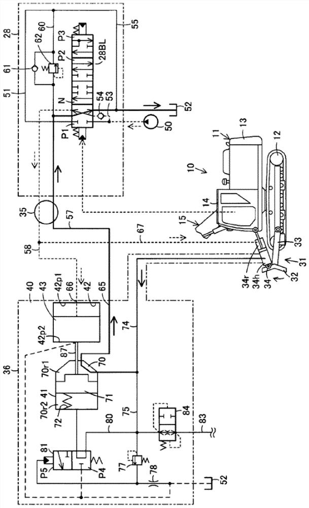
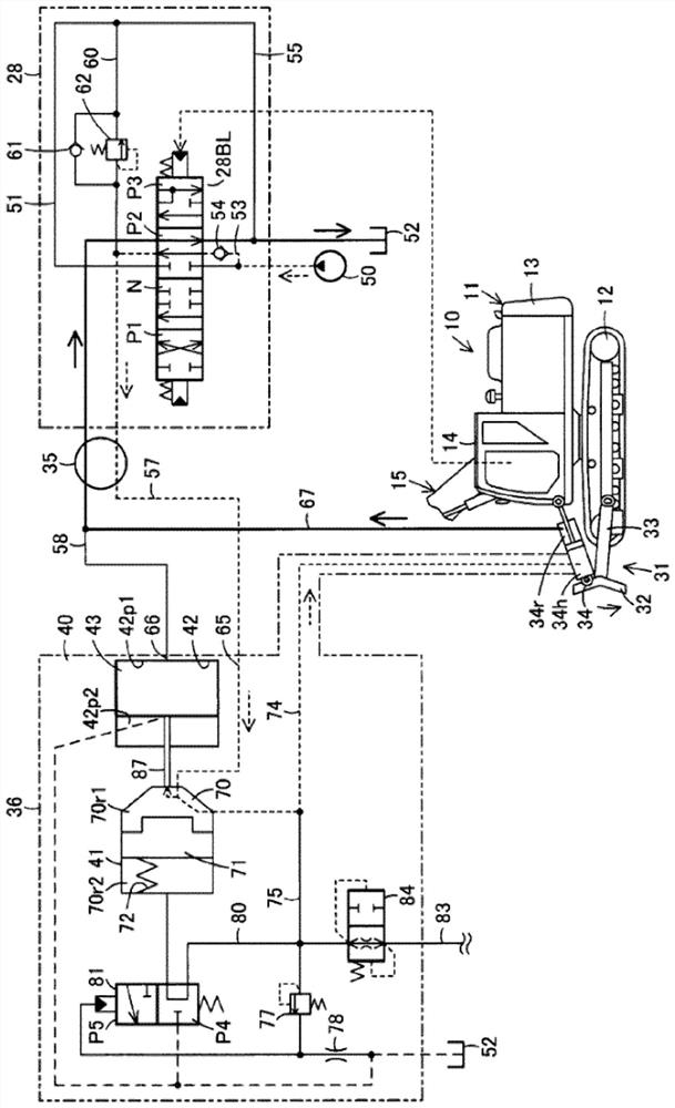
[0045] Below, based on Figure 1 to Figure 7 One embodiment shown describes the invention in detail.

[0046] exist Figure 1 to Figure 6 In , reference numeral 10 denotes a working machine. The working machine 10 of the present embodiment will be described by taking a hydraulic excavator-type working machine as an example.

[0047] The machine tool 10 includes a machine body 11 . In the present embodiment, the upper swing body 13 is provided so as to be swingable on the lower travel body 12 . The lower traveling body 12 may be wheeled or tracked, driven by a traveling engine. The upper swing body 13 is driven by a swing motor. The body 11 includes a cab 14 . The cab 14 is mounted on the upper swing body 13 .

[0048] In addition, the working equipment 15 is supported by the machine body 11 . The working equipment 15 includes: a boom whose base is articulated with the upper swing body 13 so as to be freely rotatable in the vertical direction; an arm serving as a rod ar...


PUM


Abstract

Provided are an anti-drift valve device, a blade device, and a working machine capable of operating an actuating unit with a simple structure and preventing a body from drifting. The anti-drift valve device is provided with a one-way valve 41 that allows hydraulic oil to flow from the control valve 28 to the head chamber 34h of the blade cylinder 34 and prevents the flow of hydraulic oil in the opposite direction; and accommodation with the one-way valve 41 The piston receiving portion 42 provided separately from the portion 70 is configured to movably accommodate the power piston 43 . The power piston 43 defines a first piston chamber 42pl which communicates with the rod chamber 34r of the blade cylinder 34 and a second piston chamber 42pl which is used for discharge and is positioned at the poppet valve 71 of the one-way valve 41 side and communicate with the fuel tank 52. The power piston 43 is connected to the poppet 71 of the one-way valve 41 so that the power piston 43 can be operated by the difference between the urging force of the poppet 71 of the spring 72 of the one-way valve 41 and the rod chamber pressure of the blade cylinder 34 .

Description

technical field [0001] The present invention relates to an anti-drift valve device mounted on a fluid pressure cylinder configured to move an actuating unit up and down, a blade device with the anti-drift valve device, and a working machine with the anti-drift valve device. Background technique [0002] Conventionally, among work machines such as hydraulic excavators, some are provided with a blade device for soil removal work. The blade unit can be used as an outrigger, for example, to ground the blade when digging with a bucket and to cause reaction forces from the ground associated with digging to act on the body to make it difficult to tip the body. In the case where the blade unit is used as a leg in this way, it is necessary to prevent the blade cylinder from shrinking and the body from being pinched even if the pipe connected to the blade cylinder is damaged. [0003] There is known a configuration in which, for example, a pilot type switching valve is switched by a ...

Claims


Application Information

Patent Timeline
Patent Type & Authority Patents(China)
IPC IPC(8): E02F3/815E02F9/22F15B1/00
CPCE02F9/2267E02F3/815F15B11/003F15B2013/0413F15B2211/30515F15B2211/321F15B2211/329F15B2211/355F15B13/0405F15B2211/3127F15B2211/6355E02F3/964E02F9/085E02F9/2271E02F9/2285F15B13/0401E02F9/2282F15B15/202
Inventor 居本周平喜安浩一前田宏
Owner CATEPILLAR SARL
Learn More