Large-torque output cutting transmission main body part

A high-torque, main body technology, which is applied to transmission boxes, transmission parts, driving devices, etc., can solve the problems of limited space for downhole transportation, low speed, and large front and rear width of fixed parts, so as to save installation space and reduce space Occupancy, the effect of small space occupation

Pending Publication Date: 2021-05-28
SHANGHAI TIANDI MINING EQUIP TECH CO LTD +2
View PDF0 Cites 0 Cited by
  • Summary
  • Abstract
  • Description
  • Claims
  • Application Information

AI Technical Summary

Problems solved by technology

However, in some designs, due to the consideration of the structure of the loading channel on the side of the drum, a part of the transmission of the fixed part is set above the conveyor trough, which not only affects the coal passing space, but also the front and rear width of the fixed part is too large, and the space for downhole transportation is limited; Some also set the power and main deceleration part on the side of the coal wall in front of the conveyor trough (that is, between the left and right rollers). Although the mining height can be lower, the transmission is relatively complicated, and the center of gravity of the fixed part and the swing part is relatively biased towards the coal wall. The operation of the whole machine has a certain adverse effect, especially in the condition of the undercut working face.
Even if a relatively simple transmission structure is adopted, the cutting capacity is often not easy to meet the complex conditions of working face mining because it often needs to be equipped with small and medium power multi-pole motors to achieve a low speed within a certain range.

Method used


Image

  • Large-torque output cutting transmission main body part
  • Large-torque output cutting transmission main body part
  • Large-torque output cutting transmission main body part

Examples


Embodiment Construction

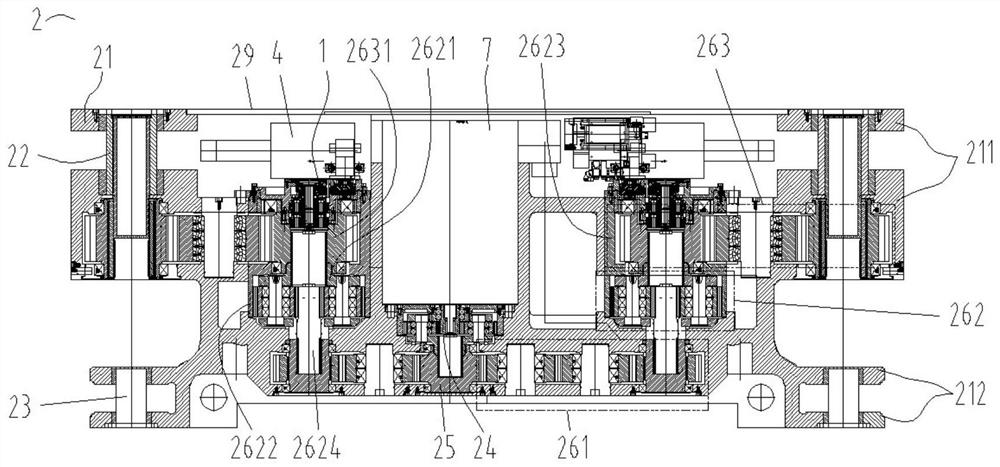
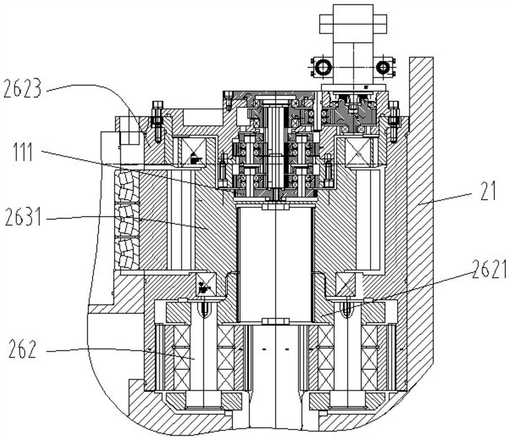
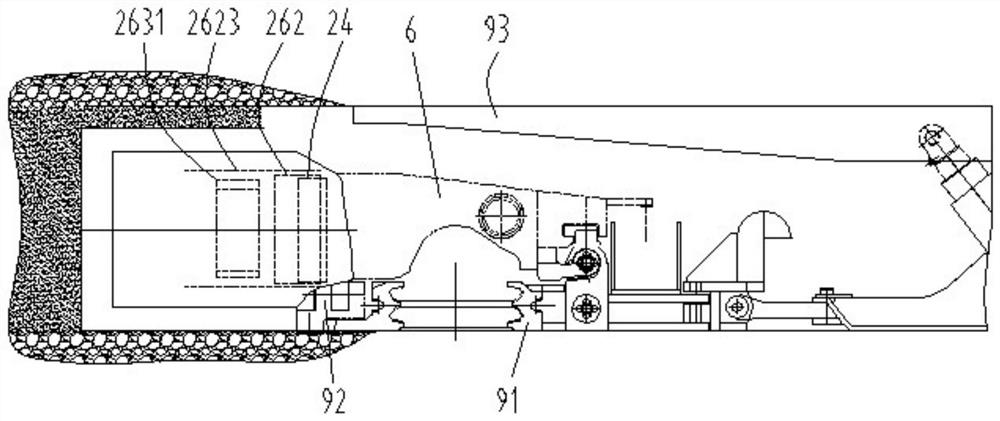
[0041] The invention discloses a large torque output cutting transmission main part, such as Figure 1-11 As shown, it includes a fixed reduction box 2, and the fixed reduction box includes a fixed reduction box housing 21 and an oil cylinder 4, a cutting motor 7 and a front-stage cutting transmission mechanism arranged in the fixed reduction box housing. The cutting transmission mechanism includes a first-stage planetary reduction mechanism 24, a central gear 25, and two sets of left and right large reduction ratio transmission mechanisms that are sequentially connected, and the large reduction ratio transmission mechanism includes a first fixed axis gear transmission mechanism 261 that is sequentially connected , a high-speed planetary reduction mechanism 262 and a second fixed shaft gear transmission mechanism 263. The first fixed-axis gear transmission mechanism, the high-speed planetary reduction mechanism and the second fixed-axis gear transmission mechanism are arranged...


PUM


Abstract

The invention relates to a large-torque output cutting transmission main body part which comprises a fixing reduction gearbox shell, and an oil cylinder, a cutting motor and a preceding-stage cutting transmission mechanism which are arranged in the fixing reduction gearbox shell; the preceding-stage cutting transmission mechanism comprises a first-stage planetary reduction mechanism, a central gear, a left group and a right group of large-reduction-ratio transmission mechanisms; each large-reduction-ratio transmission mechanism comprises a first fixed shaft gear transmission mechanism, a high-speed-stage planetary speed reduction mechanism, and a second fixed shaft gear transmission mechanism which are sequentially connected in a transmission mode and sequentially arranged from back to front; the cutting motor is a four-pole or six-pole motor; an output shaft of the cutting motor is provided with an outer spline; the outer spline is in spline connection with an internal spline at the core part of a sun gear of the first-stage planetary reduction mechanism; and the oil cylinder is positioned in front of the second fixed shaft gear transmission mechanism. The large-torque output cutting transmission main body part has large output torque, so that the loading channel and underground transportation problems can be considered, and the overall layout is beneficial to improvement of the gravity center of a whole coal mining machine.

Description

technical field [0001] The invention relates to a large-torque output cutting transmission main body, which is suitable for coal shearers with high power, short fuselage and wide mining range. Background technique [0002] In the mining of thin coal seam lower limit or extremely thin coal seam conditions, in order to improve the adaptability of the cutting swing rocker to the coal seam, the cutting transmission system is usually set to consist of two parts: the fixed part of the short structure with power and the swing part of the output power . However, in some designs, due to the consideration of the structure of the loading channel on the side of the drum, a part of the transmission of the fixed part is set above the conveyor trough, which not only affects the coal passing space, but also the front and rear width of the fixed part is too large, and the space for downhole transportation is limited; Some also set the power and main deceleration part on the side of the coal...

Claims


Application Information

Patent Timeline
IPC IPC(8): E21C31/02F16H57/02F16H57/021F16H57/023F16H57/025F16H57/029F16H57/08
CPCE21C31/02F16H57/02F16H57/021F16H57/023F16H57/025F16H57/029F16H57/08F16H2057/02034F16H2057/02069F16H2057/02086
Inventor 章立强董超林杭胡滔胡璟宋振顾恩洋丁海春王振乾郭岱钱立全余会挺黄忠东方兴吴振毅翁洋洋李璐王兆胜吴磊阚文浩
Owner SHANGHAI TIANDI MINING EQUIP TECH CO LTD
Why Eureka
Try Eureka