
Small-displacement rod type oil well pump with annular plunger

A technology of annular column and small displacement, which is applied in the field of oil well pump and annular plunger small displacement rod oil well pump, which can solve the problems of difficulty in reducing the theoretical displacement of the oil well pump, low pump efficiency, pump jam, etc., and achieve the reduction of oil extraction pipes Operation, workload reduction, avoiding the effect of stuck pump

Inactive Publication Date: 2014-06-25
XI'AN PETROLEUM UNIVERSITY
View PDF5 Cites 2 Cited by
  • Summary
  • Abstract
  • Description
  • Claims
  • Application Information

AI Technical Summary

Problems solved by technology

[0003] In order to overcome the deficiencies of the above-mentioned prior art, the object of the present invention is to provide a small-displacement rod-type oil well pump with annular plunger, which can solve the problems caused by low pump efficiency due to the difficulty in reducing the theoretical displacement of the existing oil well pump and the influence of bottom-hole sediment. Technical problems of stuck pumps and blockages

Method used


Image

  • Small-displacement rod type oil well pump with annular plunger
  • Small-displacement rod type oil well pump with annular plunger
  • Small-displacement rod type oil well pump with annular plunger

Examples


Embodiment Construction

[0019] The structural principle and working principle of the present invention will be further described in detail below in conjunction with the accompanying drawings.

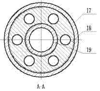
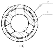
[0020] see figure 1 , 2, a small displacement rod oil well pump with annular plunger, comprising an outer pump barrel 16, an inner pump barrel 15, and an annular plunger 14, and an annular plunger assembly is fitted between the outer pump barrel 16 and the inner pump barrel 15 14. The upper end of the outer pump cylinder 16 is connected with the extension collar 10, and the upper end of the extension collar 10 is connected with a support cup assembly, and the support cup assembly is provided with a support cup reducing joint 9 and a support cup assembly from bottom to top. Press cap 8, lower supporting cup 7, supporting cup seat ring 6, upper supporting cup 5 and supporting cup mandrel 4, the upper end of supporting cup assembly is connected with valve stem guide sleeve 3,

[0021] The lower end of the outer ...


PUM


Abstract

A small-displacement rod type oil well pump with an annular plunger comprises an outer pump barrel, an inner pump barrel and the annular plunger. The upper end of the outer pump barrel is connected with a supporting leather cup assembly through a lengthening coupling, and the lower end of the outer pump barrel is connected with a valve housing of an oil inlet valve through a pump barrel coupling. The upper end of the inner pump barrel is connected with a sealing segment joint, and the lower end of the inner pump barrel is connected with the pump barrel coupling through a valve housing of an oil outlet valve. An annular work cavity is formed between the inner pump barrel and the outer pump barrel, the annular plunger is in small clearance fit with the inner pump barrel and the outer pump barrel, the annular plunger is connected with a valve rod through a valve rod lower joint, and the lower end of the valve housing of the oil inlet valve is connected with a tail pipe joint in a threaded mode through the lower joint. The annular plunger moves upwards along with the oil pump, an oil outlet valve ball is closed, an oil inlet valve ball is opened, well fluid is sucked in, fluid with a receding size of the plunger is discharged out of a well mouth, the oil inlet valve is closed, and well fluid stops from entering. In the downstroke, fluid in a pump cavity is extruded downward, and liquid is discharged into an oil pipe through a liquid outlet of a valve rod guiding sleeve after passing through the oil outlet valve assembly. The small-displacement rod type oil well pump with the annular plunger has the advantages of being high in efficiency and free of pump seizure and blocking.

Description

technical field [0001] The invention belongs to the technical field of petroleum exploitation and relates to an oil well pump, in particular to an annular plunger small displacement rod type oil well pump. Background technique [0002] With the development of the world's oil and gas industry, the proportion of easily developed conventional oil and gas resources in the total remaining oil and gas resources is getting smaller and smaller. Therefore, in the past, ultra-low permeability oilfields with poor reservoir properties, low single-well production and difficult development have become the main battlefield for oil and gas development in my country. In such oilfields, due to the low liquid supply capacity of the formation and the impact of sand production in the formation, it is easy to cause low efficiency of the conventional oil pumping system and serious mud and sand stuck in the pump. The main problems are as follows: 1) The minimum theoretical displacement of the conv...

Claims


Application Information

Patent Timeline
IPC IPC(8): F04B47/12
Inventor 屈文涛孙旭光袁比飞曹满利李宁
Owner XI'AN PETROLEUM UNIVERSITY
Learn More