Multifunctional solid plunger tube oil well pump

A solid column and oil well pump technology is applied in the field of oil well pump and multifunctional solid plunger tubular well pump. The effect of preventing sediment clogging

Active Publication Date: 2016-04-13
RES INST OF SHAANXI YANCHANG PETROLEUM GRP
View PDF7 Cites 0 Cited by
  • Summary
  • Abstract
  • Description
  • Claims
  • Application Information

AI Technical Summary

Problems solved by technology

[0002] In recent years, ultra-low permeability oil fields have become the main battlefield for domestic oil and gas development. Due to the low liquid supply capacity of the formation and the impact of sand production in the formation, it is easy to cause low efficiency of the conventional pumping system and serious mud and sand stuck pumps
The main problems are as follows: 1. The minimum theoretical displacement of the conventional oil well pump is greater than the liquid supply volume of the formation, resulting in low pump efficiency and poor mechanical efficiency. The conventional plunger is limited by the diameter of the internal flow channel and the size of the swimming valve. The diameter of the pump cannot be too small, which is difficult to Reduce the theoretical displacement of the oil well pump; 2. The conventional oil well pump has no sand control function, and the pump valve is easily blocked by sand due to the influence of sand at the bottom of the well

Method used


Image

  • Multifunctional solid plunger tube oil well pump
  • Multifunctional solid plunger tube oil well pump

Examples


Embodiment Construction

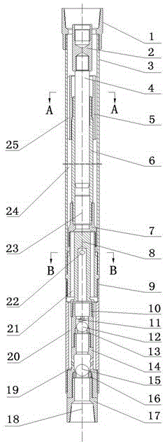
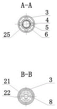
[0015] The structural principle and working principle of the present invention will be further described in detail below in conjunction with the accompanying drawings.

[0016] to combine figure 1 , figure 2 , the present invention includes an outer pump barrel 3 and an inner pump barrel 6, the upper end of the outer pump barrel 3 is connected to a tubing collar 1, a solid plunger assembly is installed in the inner pump barrel 6, and the top end of the solid plunger 4 is connected to a plunger joint 2, The upper end of the plunger joint 2 is connected to the sucker rod, and the working chamber 23 is formed between the bottom of the solid plunger 4 and the inner pump barrel 6. The pump barrel 3 is connected, and the upper oil outlet annulus 24 is formed between the inner pump barrel 6 and the outer pump barrel 3. The diversion joint 8 is connected to the backwash fixed valve cover 14 through the extension short pipe 9, and the backwash fixed valve cover 14 The lower liquid i...


PUM


Abstract

The invention relates to a multifunctional solid plunger piston tubing pump. The multifunctional solid plunger piston tubing pump comprises an outer pump cylinder and an inner pump cylinder, wherein the upper end of the outer pump cylinder is connected with an oil tube connecting hoop, the inner pump cylinder is internally provided with a solid plunger piston assembly, the top end of a solid plunger piston is connected with a plunger piston connector, the upper end of the plunger piston connector is connected with a pumping rod, the inner pump cylinder is connected with the upper end of a flow guide connector through an axle tube, the upper end of the flow guide connector is connected with the outer pump cylinder, the lower part of the outer wall of the flow guide connector is connected with a lengthened short tube, the inner wall of the flow guide connector is connected with an oil outlet valve cover, the oil outlet valve cover is internally provided with an oil outlet valve ball, an oil outlet valve seat is fixedly arranged at the upper end of a backwashing type standing valve cover, the backwashing type fixing valve cover is internally provided with a standing valve ball and a standing valve seat, and the bottom of the backwashing type standing valve cover is connected with a tail tube connector. According to the multifunctional solid plunger piston tubing pump disclosed by the invention, the theoretical discharging capacity of the pump can be greatly reduced, the mining requirement of an ultra-low-permeability oil field can be more adapted to, the standing valve ball can be subjected to flushing and backwashing, and the standing valve can be prevented from being blocked by sediments.

Description

technical field [0001] The invention belongs to the technical field of petroleum exploitation, and relates to an oil well pump, in particular to a multifunctional solid plunger tube type oil well pump. Background technique [0002] In recent years, ultra-low permeability oilfields have become the main battlefield for domestic oil and gas development. Due to the low liquid supply capacity of the formation and the impact of sand production in the formation, it is easy to cause low efficiency of the conventional pumping system and serious mud-sand pump jamming. The main problems are as follows: 1. The minimum theoretical displacement of the conventional oil well pump is greater than the liquid supply volume of the formation, resulting in low pump efficiency and poor mechanical efficiency. The conventional plunger is limited by the diameter of the internal flow channel and the size of the swimming valve. The diameter of the pump cannot be too small, which is difficult to Reduce ...

Claims


Application Information

Patent Timeline
Patent Type & Authority Patents(China)
IPC IPC(8): F04B47/00F04B53/14F04B53/16
Inventor 赵亚杰申峰高庆华黄华王卫刚刘通姚军雷茹展转盈
Owner RES INST OF SHAANXI YANCHANG PETROLEUM GRP
Why Eureka
Try Eureka