Automatic cold bending device for building construction embedded steel bars

A technology of pre-embedding steel bars and building construction, which is applied in the direction of sound-emitting devices and instruments, which can solve the problems of overall strength reduction of buildings, easy scratching of staff, and reduction of steel bar strength, so as to reduce construction site accidents and ensure the bending effect of steel bars , Improve the effect of processing speed

Inactive Publication Date: 2021-05-28
张明
View PDF0 Cites 0 Cited by
  • Summary
  • Abstract
  • Description
  • Claims
  • Application Information

AI Technical Summary

Problems solved by technology

[0003] However, the existing steel bar bending is often a semi-automatic process, which requires workers to manually switch materials and manually cut and cut the materials, resulting in low work efficiency and requiring a lot of manpower and material resources, resulting in increased construction costs. The sharp cut of the steel bar is easy to scratch the staff, causing certain safety hazards
[0004] And in the steel bar bending process, the hot bending of the steel bar will eliminate the pre-tension stress inside the steel bar and reduce the strength of the steel bar, resulting in a decrease in the quality of the building. , the cold shrinkage of the steel bar causes a cavity to form between the steel bar and the cement, resulting in a decrease in the overall strength of the building. In order to eliminate the high temperature generated during the cutting process of the steel bar and the internal high temperature generated by the steel bar in other processing or environments, the existing The rebar bending unit needs some improvement

Method used


Image

  • Automatic cold bending device for building construction embedded steel bars
  • Automatic cold bending device for building construction embedded steel bars
  • Automatic cold bending device for building construction embedded steel bars

Examples


Embodiment Construction

[0027] The following will clearly and completely describe the technical solutions in the embodiments of the present invention with reference to the accompanying drawings in the embodiments of the present invention. Obviously, the described embodiments are only some, not all, embodiments of the present invention. Based on the embodiments of the present invention, all other embodiments obtained by persons of ordinary skill in the art without making creative efforts belong to the protection scope of the present invention.

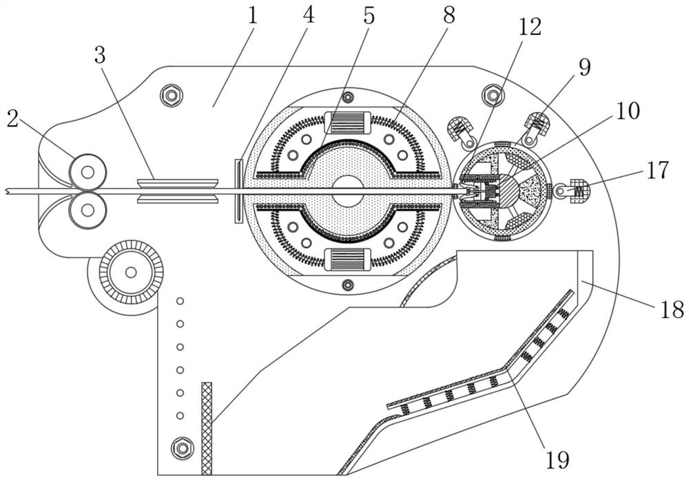
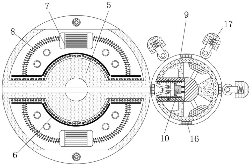
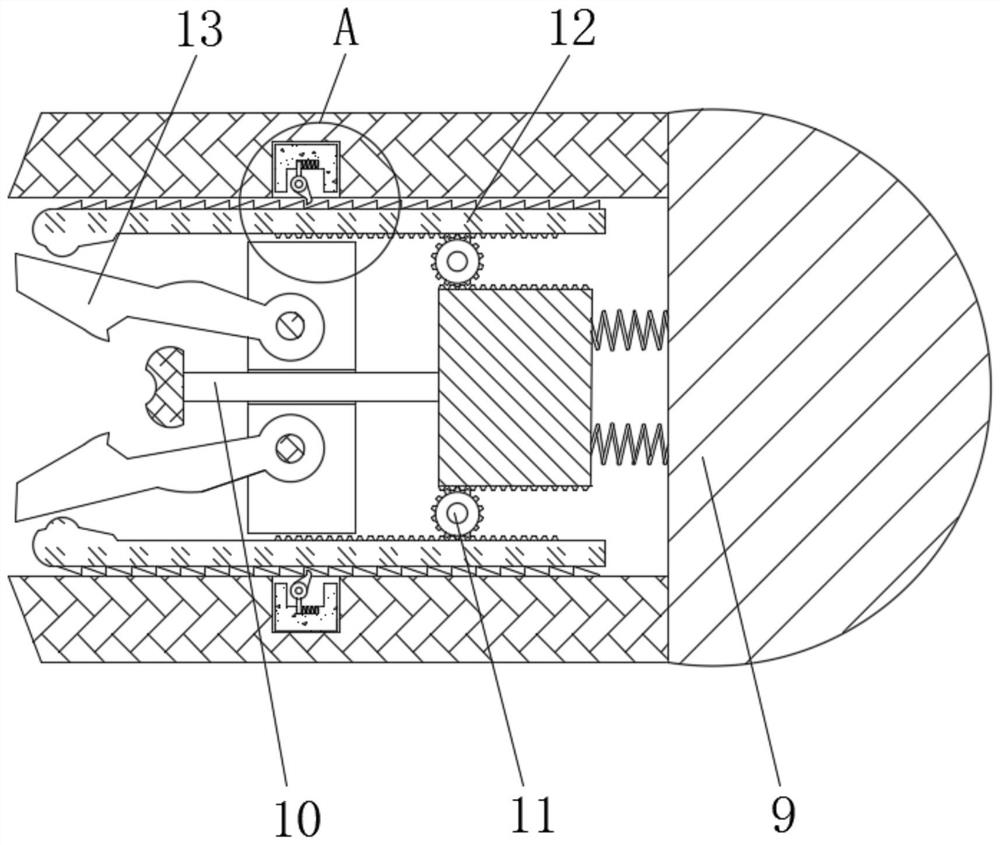
[0028] see Figure 1-6 , an automatic cold bending device for pre-embedded steel bars in building construction, including a frame 1, a feed wheel 2, a material guide wheel 3, a cutting blade 4, a cooling plate 5, a condensation pipe 6, a circulation pump 7, and a refrigeration pipe 8 , bearing plate 9, pressure block 10, connecting gear 11, limit rod 12, clamp block 13, limit claw 14, top block 15, unloading plate 16, hydraulic pump 160, pressure wheel 17, rec...


PUM


Abstract

The invention relates to the technical field of building construction equipment, and discloses an automatic cold bending device for building construction embedded steel bars. The automatic cold bending device comprises a rack, wherein feeding wheels and a guiding grooved wheel are arranged outside the rack, a cutting blade is movably connected to the interior of the rack, a cooling disc is movably connected to the side, away from the guiding grooved wheel, of the cutting blade, a condensation pipe is arranged in the cooling disc, a circulating pump is arranged in the condensation pipe, and a refrigeration pipe is connected to the exterior of the condensation pipe in a winding mode. Through the cooperative use of the cooling disc, the condensation pipe, the circulating pump and the refrigeration pipe, the effect of cooling the steel bars is effectively achieved, internal high temperature generated by cutting, other machining technologies or other factors in the steel bars is eliminated, the influence of temperature on a steel bar bending technology is reduced, the steel bars can be subjected to the cold bending technology, then the strength and internal pretension stress of the steel bars are effectively guaranteed, the steel bars are prevented from generating cooling shrinkage after pouring, and thus the strength and quality of a building object are guaranteed.

Description

technical field [0001] The invention relates to the technical field of building construction equipment, in particular to an automatic cold bending device for pre-embedded steel bars in building construction. Background technique [0002] The development of society is accompanied by the continuous expansion of the city. In the process of urbanized building construction, in order to ensure the stability of the building and improve the seismic performance of the building, it has changed from the traditional brick-wood mixed structure and wall load-bearing structure to today's Integral frame building, in the frame building, the main load-bearing part is the overall frame, and the frame is made of cement, sandstone, and steel bars, and the steel bars need to be bent during the frame process of the steel bars. [0003] However, the existing steel bar bending is often a semi-automatic process, which requires workers to manually switch materials and manually cut and cut the material...

Claims


Application Information

Patent Timeline
Patent Type & Authority Applications(China)
IPC IPC(8): B21F1/00B21F11/00B21F23/00G10K11/16
CPCB21F1/00B21F11/00B21F23/00G10K11/16
Inventor 不公告发明人
Owner 张明
Why Eureka
Try Eureka